Device for connecting a fan blade to a rotor of a ceiling fan motor

a ceiling fan and rotor technology, applied in the direction of liquid fuel engines, marine propulsion, vessel construction, etc., can solve the problems of user injury, user loss of balance, and increased installation time and cost,

Inactive Publication Date: 2001-04-03
CHIEN LUEN INDS
View PDF24 Cites 52 Cited by
  • Summary
  • Abstract
  • Description
  • Claims
  • Application Information

AI Technical Summary

Benefits of technology

The second object of this invention is to provide a device for attaching a fan blade mounting arm to a ceiling fan motor that eliminates losing fasteners such as screws.
The sixth object of this invention is to evenly attach all the fasteners that connect a ceiling fan blade to a ceiling mounted motor to eliminate wobble effects when running the ceiling fan.
A second embodiment of the captive fastener has a fastener held captive in a floating position in the mounting arm through-hole. A head of the fastener can be to one side of a ledge in a through-hole within the mounting arm. The threaded end of the fastener can have a larger diameter than a narrow neck portion of the fastener so that the neck portion is located between the fastener head and the threaded end, and the threaded end being positioned to a second side of the ledge opposite the first side. The narrow neck of the fastener can move upward and downward a selected distance about the ledge. A tip portion of the fastener can protrude through an upper side of the mounting arm for guiding the mounting arm to the mateable opening on the rotating member. The heads of the captive fasteners in both the first and second embodiment can be like a regular headed screw, a Philips head screw and a bolt. An optional spring locking washer can help lock the tightened fastener in place.
The third embodiment of the invention includes an alignment post and a mateable opening for receiving the alignment post, for allowing the mounting arm to be correctly aligned in position onto the rotating member. The post can extend upward from the mounting arm with a mateable receiving opening on the bottom of the rotating member. Alternatively, the alignment post can extend downward from the rotating member with the receiving opening on the mounting arm. The post can have tapered length with rounded sides so that pushing the post into the receiving opening snugly connects the mounting arm to the rotating member on the ceiling fan motor. Another version of the post has flat side portions such as those found in a square, rectangle, hexagon and the like, with the receiving opening having like configurations, thus creating a fixed position for connecting the mounting arm to the rotating member. Another version includes a second alignment post and a second mateable opening for receiving the second alignment post. With two alignment posts, only one captive fastener needs to be used Still another version allows the alignment posts to be used with existing non captive fasteners, such as but not limited to regular and Philips head screws, bolts, and the like. The novel alignment posts also eliminate known wobbling effects since the posts allow the mounting arms to be evenly attached to the motor.

Problems solved by technology

Many problems occur from this traditional method of having one person installing a ceiling fan.
Screws 50 can and do accidentally fall and become lost causing more time and more expense to finish the installation.
The blade 30 and mounting arm 40 have been known to fall on and cause injury to the user 60 during assembly.
Additionally, the user can lose their balance and injure themselves as well falling off the ladder and stool.
Additional problems also occur after installation.
For example, uneven tightening of each of the plural fasteners that connect the mounting arm to the motor has resulted in wobble effects when the ceiling fan system is running.
Thus, the current operation of assembly has become known as a frustrating, undesirable, difficult, tedious, time consuming and sometimes dangerous task.
To merely add a second worker to help in the assembly installation may solve some of the problems above, but would add additional cost and labor expense to the installation project.

Method used


Image

  • Device for connecting a fan blade to a rotor of a ceiling fan motor
  • Device for connecting a fan blade to a rotor of a ceiling fan motor
  • Device for connecting a fan blade to a rotor of a ceiling fan motor

Examples


second embodiment

FIG. 3A is a perspective view of a novel captive fastener 250 with an optional spring locking washer 260 used for the second embodiment 200. FIG. 3B is a side cross-sectional view of a second embodiment 200 of using two of the novel captive fasteners 250 and spring washers 260 of FIG. 3A with a mounting arm 240, rotor 20, and bottom endshield 22 that is connected to a ceiling fan motor 10. FIG. 3C is an enlarged side view of the unattached fastener F1 of FIG. 3B. FIG. 3D is an enlarged side view of the attached fastener F2 of FIG. 3B.

Referring to FIGS. 3A-3D, the fasteners 250 are already held captive in one end of the mounting arm 240 and the opposite end of the mounting arm is already connected to a fan blade (not shown). Fasteners 250 can have a threaded end portion 255 with a diameter larger than a base neck portion 256 and a large head portion 252. The narrow base neck portion 256 between the threaded end 255 and the head 252 allows the fastener 250 to freely float therebetween...

third embodiment

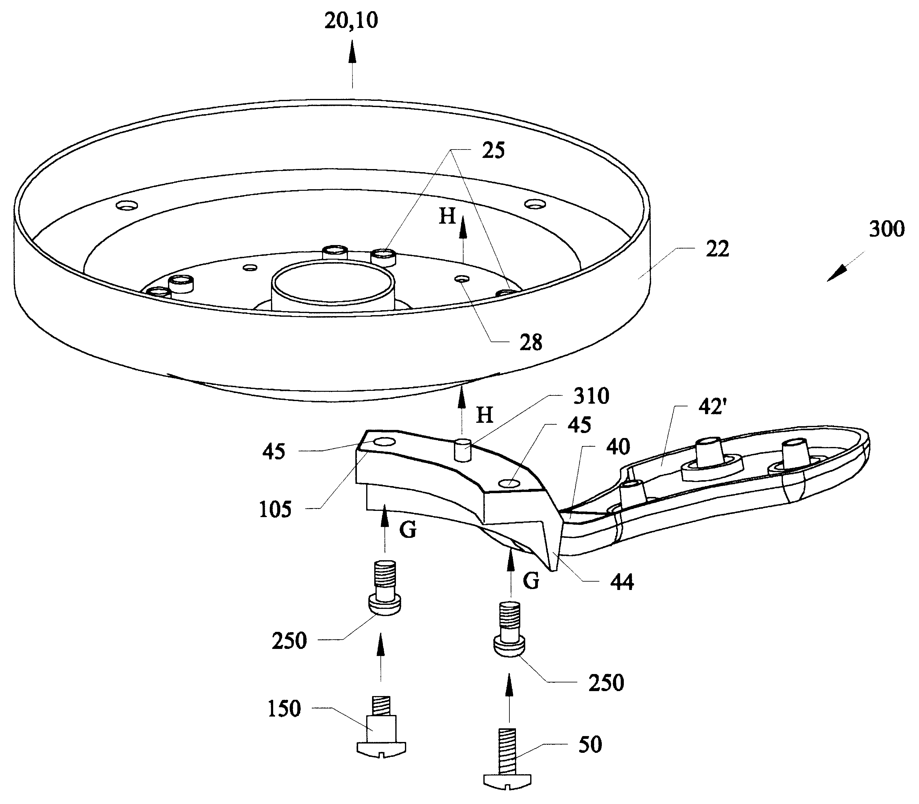
FIG. 4A is a perspective exploded view of a third embodiment 300 of using either or both the captive fasteners 150, 250 of the preceding Figures, or a conventional fastener 50 with an alignment post 310 for attaching the mounting arm 40 to the a ceiling fan motor 10. Referring to FIG. 4A, an alignment post 310 having tapered rounded sides with a narrow tip portion and an expanding bottom portion is located approximately half way between through-holes 45 in end 44 of blade mounting arm 40. Opposite end 42' of blade arm 40 has attachment points similar to those previously described. An opening 28 having a diameter the same as or slightly smaller than the diameter of the base portion of post 310 is located in the bottom of motor endshield 22.

Similar to that previously described, bottom endshield 22 is attached to a rotating rotor 20 which is attached to a ceiling mounted motor 10. Next as previously described, captive fasteners 250, 150 with or without rubber grommet washer 101 have th...


PUM


Abstract

Captive fasteners and alignment posts for allowing ceiling fan blade arms to be easily and safely mounted onto ceiling mounted motors. Fasteners such as Philips head screws, regular head screws and bolts can be held captive in place on blade mounting arms with rubber grommet type washers. The grommet type washers have portions that can be sandwiched between the fastener head and the mounting arms and sandwiched between the mounting arms and rotating member on the ceiling fan motor in order to reduce vibration noise and movement Alternatively, novel captive fasteners having a thicker neck portion between a threaded end a the bead can be positioned within the grommet type washers. A second embodiment of the captive fastener is floatingly supported within the mounting arm between the fastener head and a ledge within the mounting arm through-hole, with an enlarged threaded end of the fastener on the opposite side of the ledge. A tip portion of these captive fasteners can remain extended from the upper surface of the mounting arm and is used to guide the fasteners to the mateable threaded openings on the bottom of the rotating member on the motor. A third embodiment incorporates at least one alignment post and mateable receiving hole for allowing the mounting arm to be properly aligned with the correct position on the rotating member. The alignment posts can be tapered, rounded or having flat sides such as squares and hexagons, to further position and hold the mounting arms to the rotating members on the motor. The alignment post(s) can be located on the upper surface of the mounting arms or extend downward from the rotating member of the motor. With the alignment posts either or both captive fasteners or regular fasteners such as bolts, regular head and Philips head screws can be used. Additionally, the alignment post(s) can be used without the grommet shaped washers. The alignment members and captive fasteners eliminate wobble effects by evenly attaching the mounting blade arm to the ceiling fan motor.

Description

This invention relates to ceiling fans, and in particular to devices for easily connecting blade mounting arms to the rotors on ceiling fan motors using captive fasteners and alignment posts.BACKGROUND AND PRIOR ARTFIG. 1 shows a partial side view of a conventional ceiling fan unit 1 that encompasses a general prior art ceiling fan system. In FIG. 1, ceiling fan motor 10 has a rotor component 20 that rotates about a central axis beneath motor 10, which is in turn connected to a housing 5 that is attached beneath a ceiling 2. A plurality of fan blades 30 are connected to the rotor 20 by mounting arms 40. Each mounting arm 40 has one end 42 connected to an end 32 of each fan blade 30, and a second end 44 having at least two through-holes 45 therethrough, so that conventional fasteners such as screws 50 pass through the through-holes 45 to mateably thread into threaded holes 25 in the bottom of rotor 20.Usually most conventional directions have the installer first connect and hang the ...

Claims


Application Information

Patent Timeline
Patent Type & Authority Patents(United States)
IPC IPC(8): F04D25/08F04D25/02F04D29/34F04D29/32
CPCF04D25/088F04D29/34
Inventor BUCHER, CHARLES E.BUCHER, JOHN C.WU, SHIH-TZA
Owner CHIEN LUEN INDS
Why Eureka
Try Eureka