Variable magnetic monopole field electro-magnet and inductor

a magnetic monopole field, electromagnet technology, applied in the direction of magnets, magnetic bodies, magnetic circuit shapes/forms/construction, etc., can solve the problems of limiting the number of turns, hysteresis losses, and weak Sturgeon's magnets, so as to eliminate the loss of hysteresis

Inactive Publication Date: 2019-08-29
QUANTAKINETIC TECH LLC
View PDF0 Cites 0 Cited by
  • Summary
  • Abstract
  • Description
  • Claims
  • Application Information

AI Technical Summary

Benefits of technology

[0079]The invention provides a superior concentration and equally distributed magnetic field over the entire electromagnet's face or surface with a desired controllable magnetic field strength and polarity amplitude.
[0092]The present invention provides an electromagnet and inductor to eliminate the loses in the ferromagnetic core lamination by capturing the circulating Eddy currents and reintroduce them in the power supply circuit or use it as a secondary or primary inductive winding and electrical circuit.

Problems solved by technology

However, Sturgeon's magnets were weak because the uninsulated wire he used could only be wrapped in a single spaced out layer around the core, limiting the number of turns.
The prior art's typical electromagnet approach and limitation includes field lines that encircle the wire windings but do not enter the core.
The above methods are inapplicable when most of the magnetic field path is outside the core.
This model doesn't give the correct magnetic field inside the core, and thus gives incorrect results if the pole of one magnet gets too close to another magnet.
However, the limit to increasing N is that the larger number of windings takes up more room between the magnet's core pieces.
Any sudden change in the winding current cause large voltage spikes across the windings.
If an ordinary switch is used to control the winding current, this can cause sparks at the terminals of the switch.
But when it is switched off, the energy in the magnetic field is suddenly returned to the circuit, causing a large voltage spike and an arc across the switch contacts, which can damage them.
The leakage field lines between each turn of the coil exert a repulsive force between adjacent turns, tending to push them apart.
This causes energy losses in their magnetic cores that are dissipated as heat in the core.
First, Eddy currents: From Faraday's law of induction, the changing magnetic field induces circulating electric currents inside nearby conductors, called eddy currents. The energy in these currents is dissipated as heat in the electrical resistance of the conductor, so they are a cause of energy loss. Since the electromagnet's iron core is conductive, and most of the magnetic field is concentrated there, eddy currents in the core are the major problem. Eddy currents are closed loops of current that flow in planes perpendicular to the magnetic field. The energy dissipated is proportional to the area enclosed by the loop. To prevent them, the cores of AC electromagnets are made of stacks of thin steel sheets, or laminations, oriented parallel to the magnetic field, with an insulating coating on the surface. The insulation layers prevent eddy current from flowing between the sheets. Any remaining eddy currents must flow within the cross section of each individual lamination, which reduces losses greatly. Another alternative is to use a ferrite core, which is a nonconductor.
Second, Hysteresis losses: Reversing the direction of magnetization of the magnetic domains in the core material each cycle causes energy loss, because of the coercivity of the material. These losses are called hysteresis. The energy lost per cycle is proportional to the area of the hysteresis loop in the well-known BH graph. To minimize this loss, magnetic cores used in transformers and other AC electromagnets are made of “soft” low coercivity materials, such as silicon steel or soft ferrite.
Current designs are limited to 10-20 T, with the current (2009) record of 33.8 T. The necessary refrigeration equipment and cryostat make them much more expensive than ordinary electromagnets.
Both iron-core and superconducting electromagnets have limits to the field they can produce.
The factor limiting the strength of electromagnets is the inability to dissipate the enormous waste heat, so more powerful fields, up to 100 T, have been obtained from resistive magnets by sending brief pulses of current through them.
While this method may seem very destructive there are methods to control the blast so that neither the experiment nor the magnetic structure is harmed, by redirecting the brunt of the force radially outwards.
These devices are known as destructive pulsed electromagnets.

Method used


Image

  • Variable magnetic monopole field electro-magnet and inductor
  • Variable magnetic monopole field electro-magnet and inductor
  • Variable magnetic monopole field electro-magnet and inductor

Examples


Embodiment Construction

[0107]A full and enabling disclosure of the present invention, including the best mode thereof, to one skilled in the art, is set forth more particularly in the reminder of the specification, including reference to the accompanying drawings, in which the reference numerals refer to various structural and other features of the preferred embodiment as follows:

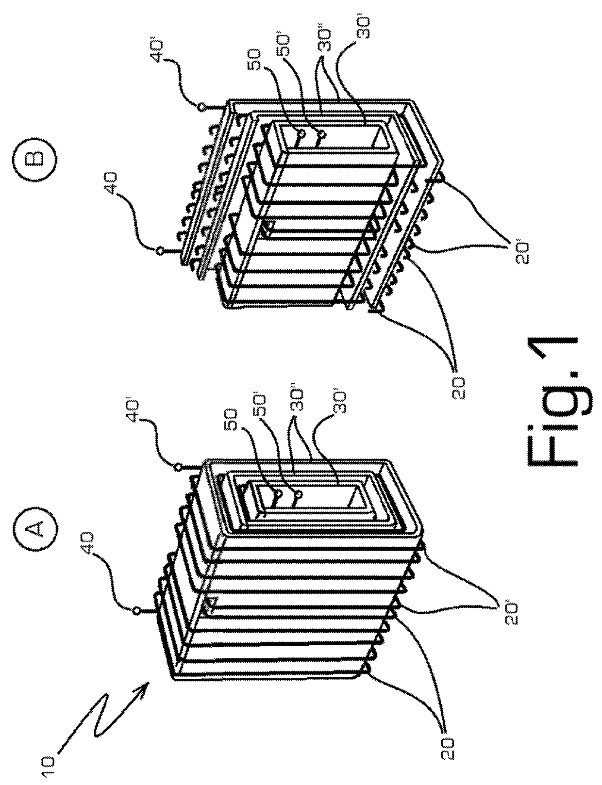
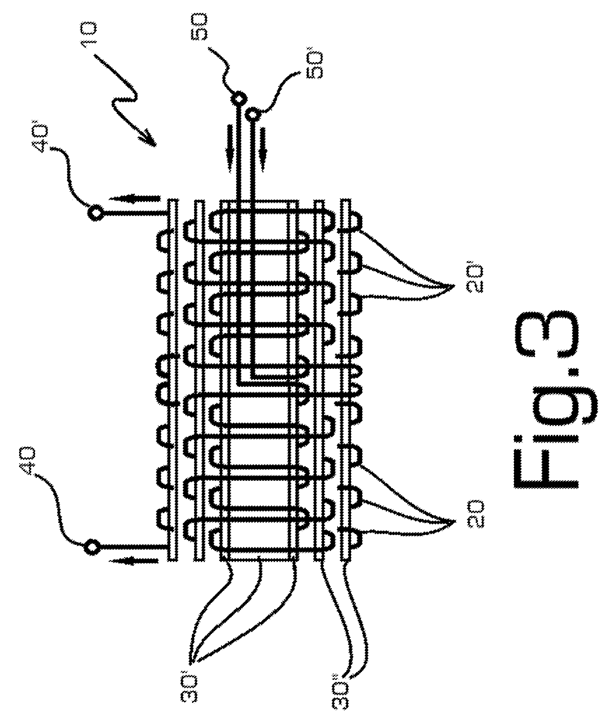
[0108]10—General view of the preferred embodiment;

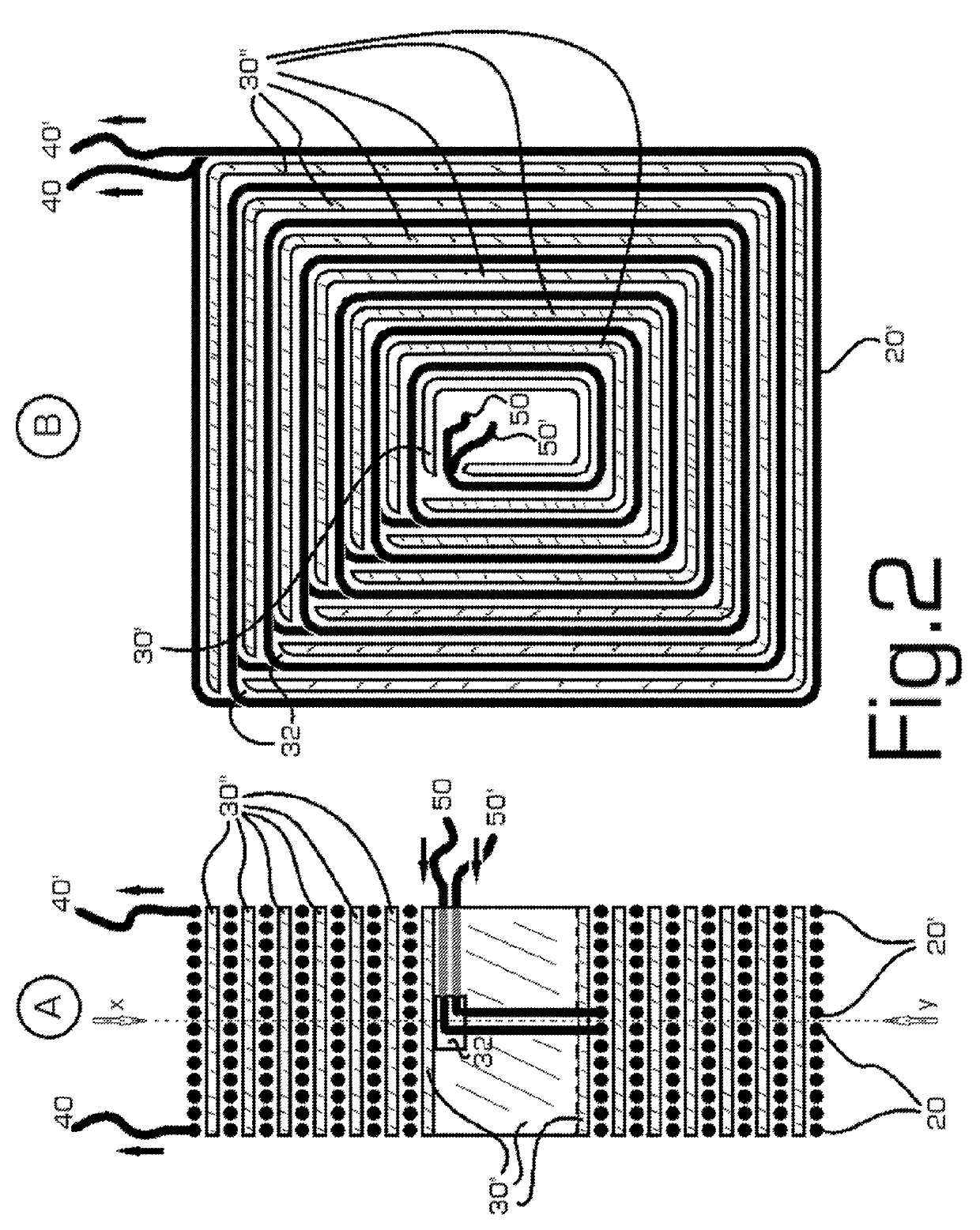
[0109]20—Winding layer sharing the same ferromagnetic interleaved lamination support with its mirrored counterpart #20′;

[0110]20′—Mirrored winding layer sharing the same ferromagnetic interleaved lamination support with winding #20;

[0111]30—Ferromagnetic lamination core support for each winding layer;

[0112]40—The external end lead of #20 winding layer;

[0113]40′—The external end lead of the mirrored #20′ winding layer;

[0114]50—The starting point lead of the winding #20;

[0115]50′—The starting point lead of the winding #20′;

[0116]60—Three position commutator panel;

[0117]70—Ferromagne...


PUM

PropertyMeasurementUnit
magnetic fieldaaaaaaaaaa
magnetic pressureaaaaaaaaaa
magnetic fieldaaaaaaaaaa

Abstract

A novel variable magnetic monopole field electro-magnet and inductor with equal and stable high density magnetic field winding system for use in any AC-DC electric motor and generator or in any AC transformer including interleaved ferromagnetic supportive cores positioned between the layers of windings.

Description

TECHNICAL FIELD[0001]The invention relates generally to the art of electro-magnets and inductors used in electric motors and generators, transformers and other electromechanical actuator machines. More particularly, the invention relates to a superior concentration equally distributed magnetic field over the entire electromagnet's generated magnetic pole face or surface with a controllable magnetic field strength and polarity amplitude through the combination of the parallel, series and / or independent winding connection system of the same coil and having interleaved laminated supportive ferromagnetic material cores between the windings layers.BACKGROUND ART[0002]As we know today, by definition, an electromagnet is a type of magnet in which the magnetic field is produced by the flow of the electric current. The magnetic field disappears when the current is turned off. A simple electromagnet consisting of a coil of insulated wire wrapped around an iron core. The strength of magnetic f...

Claims


Application Information

Patent Timeline
Patent Type & Authority Applications(United States)
IPC IPC(8): H02K1/06H02K3/04H01F27/38H01F7/20H01F7/08H02K3/28H01F27/34
CPCH02K1/06H02K3/04H01F27/38H01F27/346H01F7/08H02K3/28H01F7/202
Inventor BOJIUC, DUMITRU
Owner QUANTAKINETIC TECH LLC
Why Eureka
Try Eureka