Method and apparatus for initialization and operation of field-commutated motors and machines incorporating field-commutated motors

a field-commutated motor and field-commutated technology, applied in the direction of motor/generator/converter stopper, dynamo-electric gear control, dynamo-electric converter control, etc., can solve the problems of time-consuming manipulation, tedious initialization or re-initialization of an installed motor, and requiring additional personnel, so as to save time and effort

Inactive Publication Date: 2001-04-03
OTIS ELEVATOR CO
View PDF9 Cites 7 Cited by
  • Summary
  • Abstract
  • Description
  • Claims
  • Application Information

AI Technical Summary

Benefits of technology

The present invention addresses the above object by providing methods and apparatus for calibrating a field-commutated motor when the motor is under non-zero load. Accordingly, zeroing of the load on the motor can be avoided, saving time and effort otherwise expended in commissioning apparatus incorporating the motor therein, such as an elevator.

Problems solved by technology

Initialization, or re initialization, of an installed motor is tedious.
Such manipulation can be time consuming and require additional personnel.

Method used


Image

  • Method and apparatus for initialization and operation of field-commutated motors and machines incorporating field-commutated motors
  • Method and apparatus for initialization and operation of field-commutated motors and machines incorporating field-commutated motors
  • Method and apparatus for initialization and operation of field-commutated motors and machines incorporating field-commutated motors

Examples


Embodiment Construction

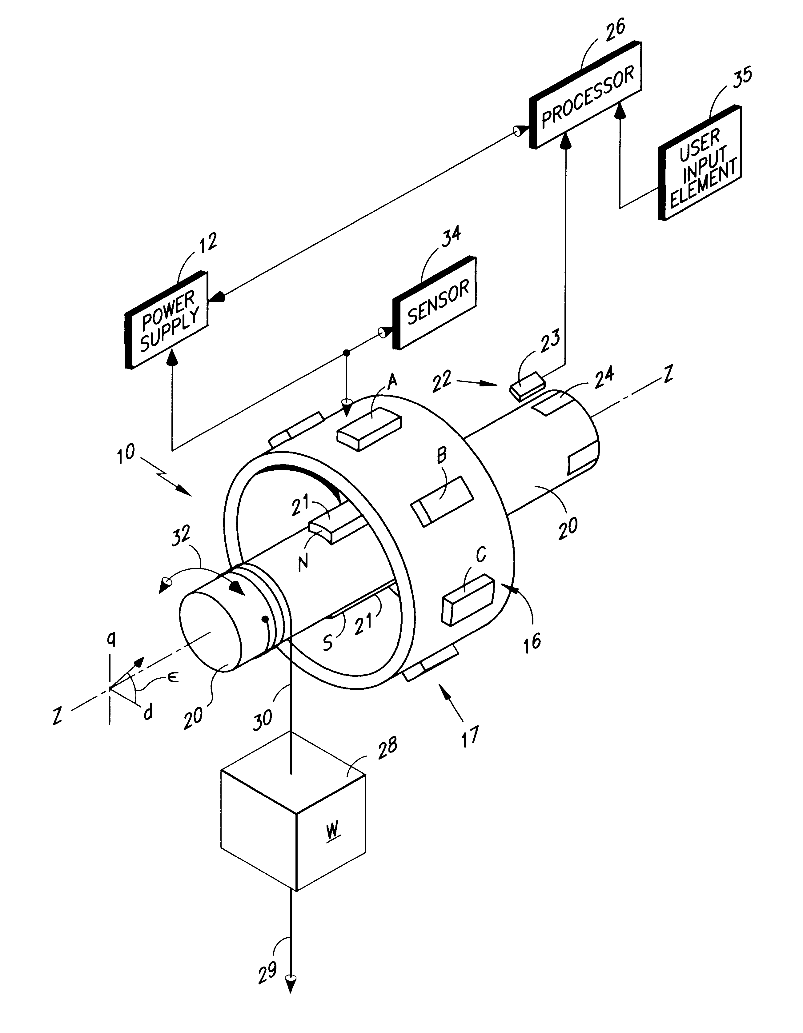
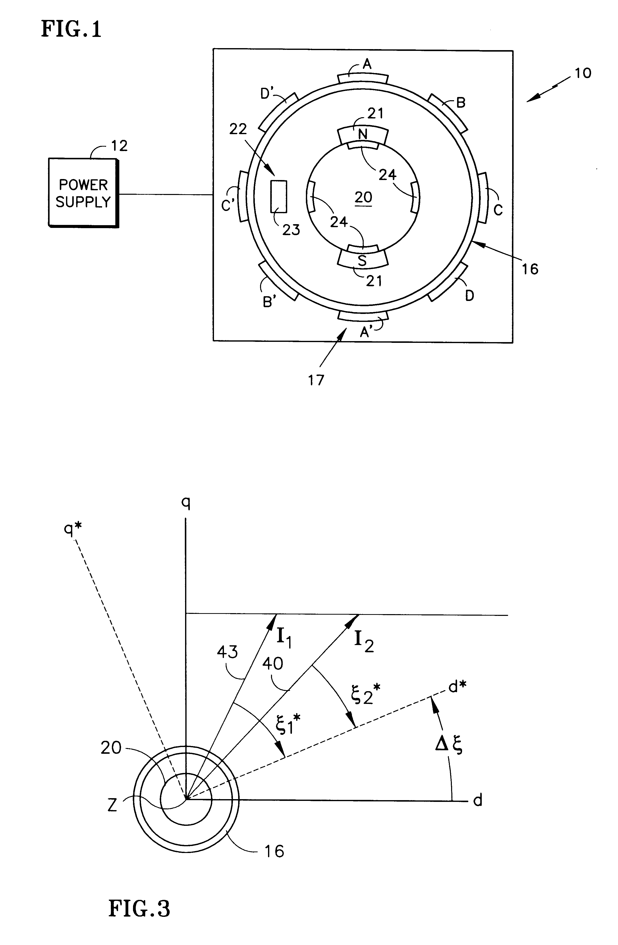
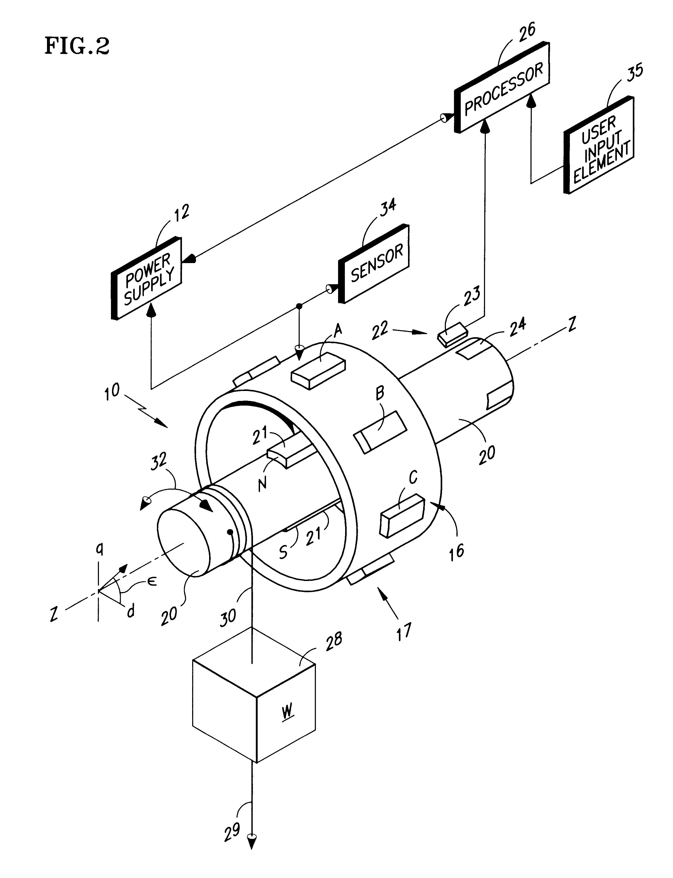
FIGS. 1 and 2 illustrate a field-commutated motor 10. FIG. 1 is a view of the motor 10 taken along the Z--Z axis of FIG. 2, which illustrates the motor 10 in perspective. The field-commutated motor 10 includes a stator 16, mounting coils 17, indicated as A-A', B-B', C-C' and D-D', and a rotor 20 mounting permanent magnets 21. The power supply 12 provides power for exciting the coils 17 in a proper sequence and with the proper timing to rotate the rotor 20 about the Z axis, as indicated by the arrow 32, and in a desired direction and with a desired speed or torque. The sensor 22, which can include a fixed element 23 cooperating with indicia 24 mounted with the rotor 20, provides information regarding the angular position of the rotor 20 such that coils 17 can be excited in the proper sequence and with the proper timing. One sensor known in the art or suitable for use as the sensor 22 is referred to as a sine-cosine encoder. The power supply 12 is typically a pulse-width-modulated (PW...


PUM


Abstract

Methods and apparatus are disclosed for calibrating a field-commutated motor (10) when under load, wherein initializing the motor (10) refers to relating data representative of the angle of the rotor in an uncalibrated coordinate system to a coordinate system having a known relationship to the excitation coils (17), typically mounted with the stator (16). The angular data can then be used for exciting the excitation coils (17) in the proper sequence and with the proper timing to obtain the desired speed, torque, direction or rotation, etc. of the motor (10). Test voltages having a known orientation are applied to one of the stator and the rotor, (whichever mounts the excitation coils (17)), and the angle of the rotor produced by the application of each of the test voltages noted. An equation is disclosed for determining an error angle between the uncalibrated and the known coordinate system as a function of the angles of the rotor produced by application of the test voltages. Apparatus for practicing the invention can include a processor (26), a power supply (12), and user input element (35) and a voltage and / or current sensor (35). The processor (26) can include appropriate means for executing the disclosed method steps.

Description

FIELD OF THE INVENTIONThis invention relates to field-commutated motors and machines incorporating such motors.BACKGROUND OF THE INVENTIONFIG. 1 shows a simple schematic of a field-commutated motor 10 powered by a power supply 12, and having a stator 16 and a rotor 20. The stator mounts excitation coils 17 (A-A', B-B', C-C' and D-D'), which are sequentially excited such that the coils act as magnets, having north and south poles, to generate forces on the permanent magnets 21 mounted on the rotor 20, thereby rotating the rotor 20. A knowledge of the position of the rotor magnets 21 relative to the coils 17 is necessary for the coils to be excited in the proper sequence and with the proper timing to provide the desired torque, speed or direction of rotation of the rotor 20. Typically, a sensor 22 provides raw data representative of the rotor angular position in a "sensor", or uncalibrated, coordinate system. However, this data must be used to determine the position of the magnets 21 ...

Claims


Application Information

Patent Timeline
Patent Type & Authority Patents(United States)
IPC IPC(8): H02P6/00H02P21/14H02P6/08H02P6/12H02P6/16
CPCH02P6/00H02P6/08H02P6/16H02P6/32
Inventor HELLER, MARCUS C.MANN, MICHAELERNECKE, CHRISTOPH
Owner OTIS ELEVATOR CO
Why Eureka
Try Eureka