
High speed interface apparatus

a high-speed, interface technology, applied in the direction of pulse conversion, pulse technique, instruments, etc., can solve the problems of increased power consumption, noise etc., at a system speed more than 100 mhz,

Inactive Publication Date: 2001-04-03
HYUNDAI ELECTRONICS IND CO LTD
View PDF18 Cites 37 Cited by
  • Summary
  • Abstract
  • Description
  • Claims
  • Application Information

AI Technical Summary

Problems solved by technology

However, the bus interface has the problems of increased power consumption, noises etc. at a system speed more than 50 MHz and also of limited high speed due to reflection of signal and occurrence of ringing.
However, it also has various problems such as increased power consumption, noises etc. at a system speed more than 100 MHz, similar to those of the TTL interface.
However, since the high speed bus interfaces have to increase the system bus frequency or widen the bus width in order to increase the bandwidth, they have problems of increased power consumption, noises, electromagnetic interference(EMI), cost etc.
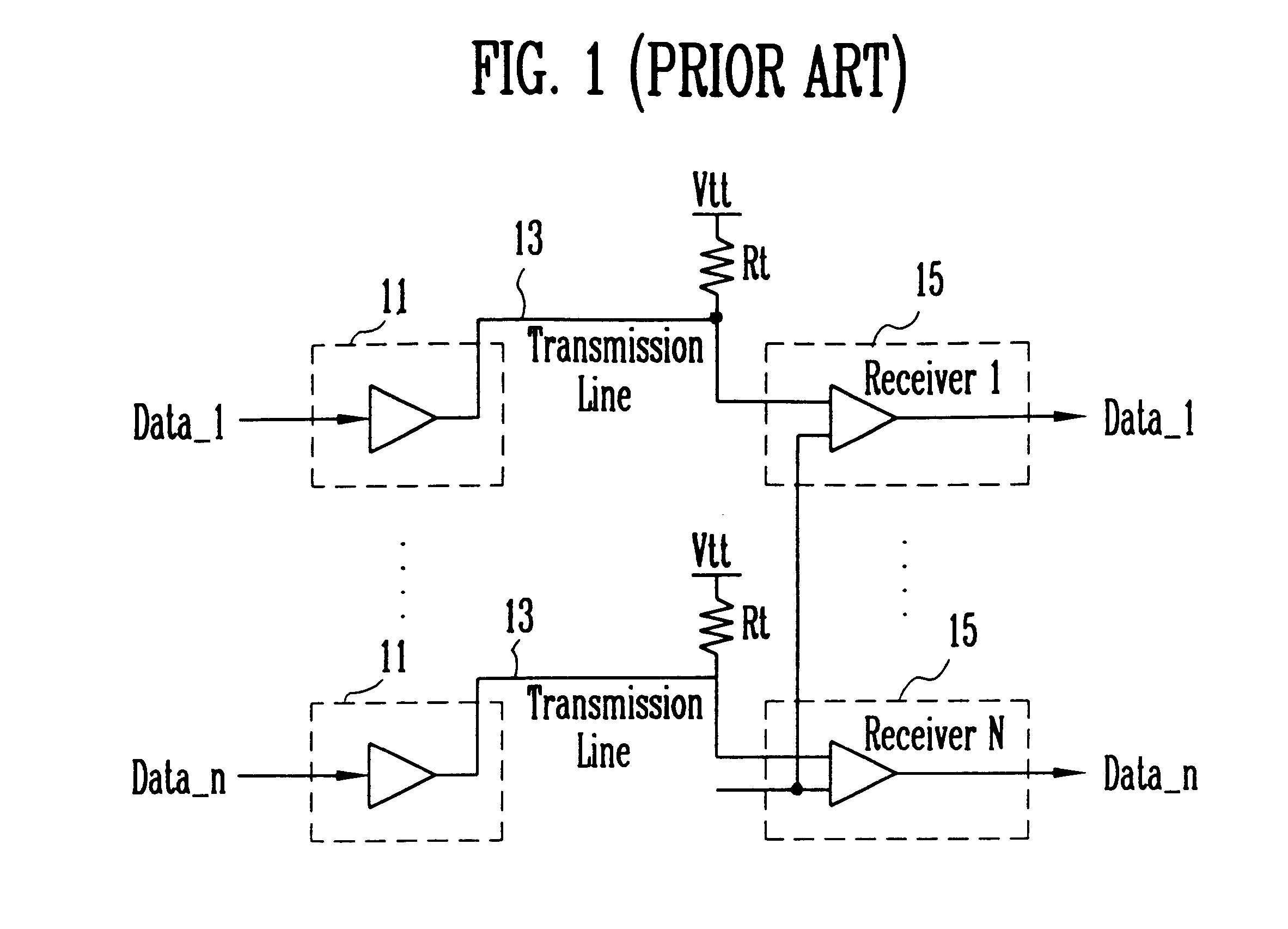
As above, the conventional interface apparatus unnecessarily requires increased bandwidth for high speed transmission.
As a result, it has the problems of increasing input / output power consumption and system cost due to increased bus frequency and bus width, and also of further occurring noises and an electromagnetic interference etc.

Method used


Image

  • High speed interface apparatus
  • High speed interface apparatus
  • High speed interface apparatus

Examples


first embodiment

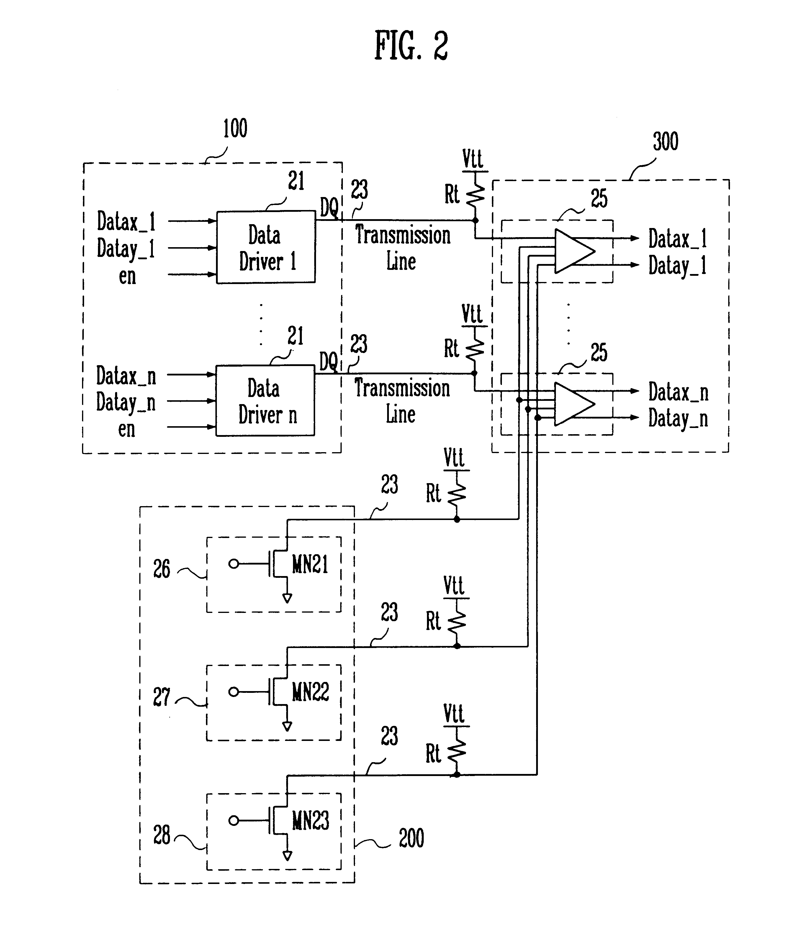
FIG. 2 shows the construction of a high speed interface apparatus according to the present invention. The high speed interface apparatus includes a data driving means 100 which is consisted of a plurality of N data drivers 21 for decoding two data signals (datax.sub.--1.about.n, datay.sub.-- 1.about.n) using them as inputs, respectively, to output two-bit data signals DQ; a reference voltage generating means 200 for generating three level reference voltages VR1 to VR3 to determine the two-bit data signals DQ; transmission lines 23 each connected to the data driving means 100 and the reference voltage generating means 200, for transmitting the two-bit data signals DQ and the three level reference voltages VR1 to VR3; a receiver means 300 which is consisted of N receiver 25, for comparing the two-bit data signals DQ transmitted by the transmission lines 23 with the three level reference voltages VR1 to VR3, respectively, and encoding the resulting signals to output two data signals (d...

second embodiment

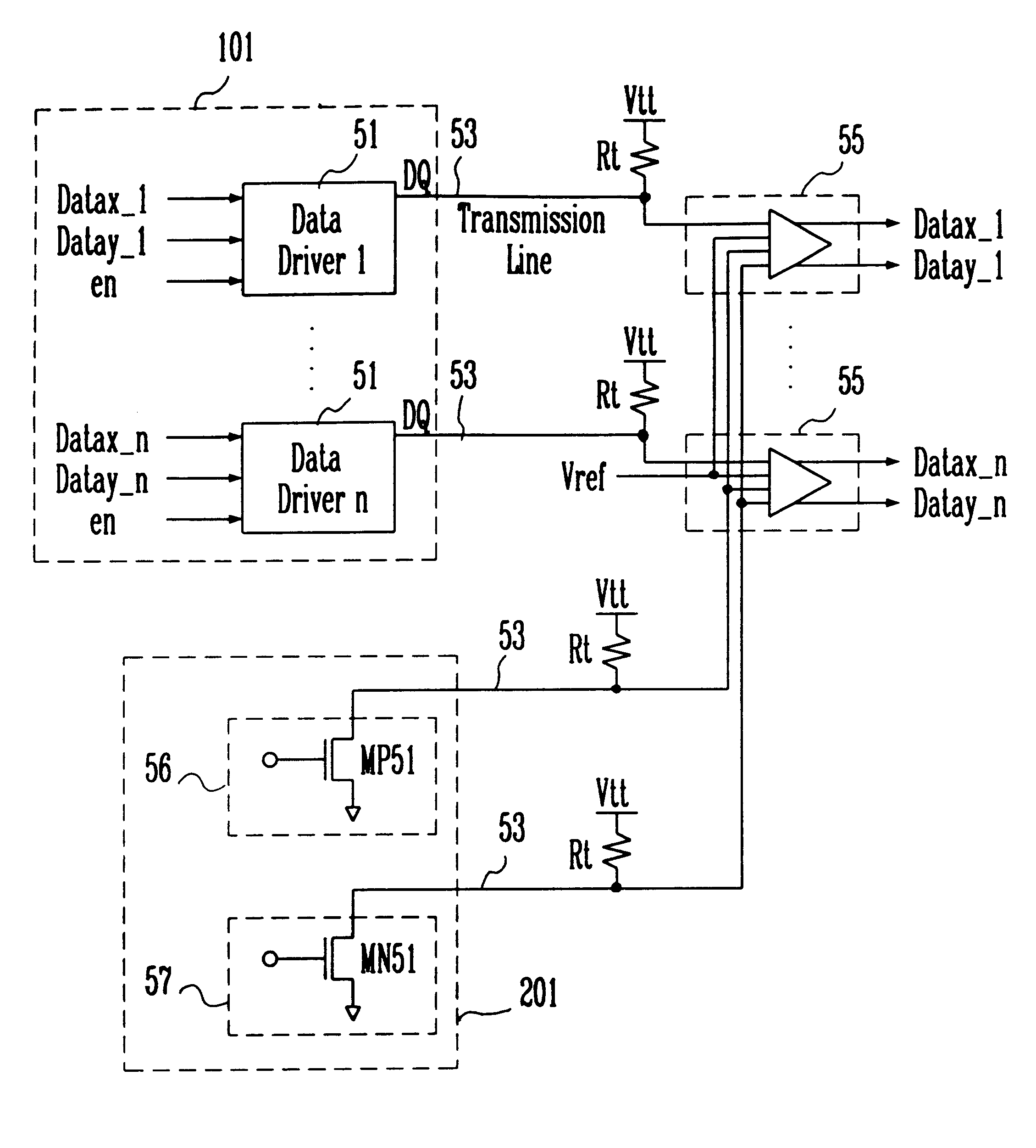
Next, FIG. 5 shows the construction of a high speed interface apparatus according to the present invention. The high speed interface apparatus includes a data driving means 101 which is consisted of a plurality of N data drivers 51 for decoding two data signals (datax.sub.-- 1.about.n, datay.sub.-- 1.about.n) using them as inputs, respectively, to output two-bit data signals DQ; a reference voltage generating means 201 for generating two-level reference voltages VR1,VR2 to discriminate the two-bit data signals DQ; transmission lines 53 each connected to the data driving means 101 and the reference voltage generating means 201, for transmitting the two-bit data signals DQ and the two-level reference voltages VR1,VR2; N receiver means 55 for comparing four-level data signals DQ transmitted by means of the transmission lines 53 with the two-level reference voltage signals VR1,VR2 and a third reference voltage Vref which is input externally (the `Vtt` is used as `Vref`), respectively, a...


PUM


Abstract

The present invention discloses a much higher speed interface apparatus which comprises a data driving means for decoding two-bit data signals using them as inputs to output four-level data signals; a reference voltage generating means for generating three-level reference voltages to discriminate the voltage levels of the four-level data signals; and a receiver means for comparing the four-level data signals and the three-level reference voltage signals using them as inputs and for encoding the resulting signals to output two data signals.

Description

1. Field of the InventionThe present invention relates to a much higher speed interface apparatus. In particular, the present invention relates to a much higher speed interface apparatus in which the bandwidth is widened twice, even with keeping the bus width and the system bus frequency thereof as they are, by provision of a reference voltage generating means for discriminating two-bit data signals.2. Description of the Prior ArtGenerally, DRAMs used in a main memory and a graphic card of the computer require a higher bandwidth for improved system performance, and thus necessitate a bus interface for switching data signals at high speed.Thus, in past twenty years, the TTL bus interface has been widely used as an industry standard. However, the bus interface has the problems of increased power consumption, noises etc. at a system speed more than 50 MHz and also of limited high speed due to reflection of signal and occurrence of ringing.To alleviate the above problems a little, conve...

Claims


Application Information

Patent Timeline
IPC IPC(8): G06F13/40
CPCG06F13/4072
Inventor SUH, JUNG WON
Owner HYUNDAI ELECTRONICS IND CO LTD
Learn More