Condition detecting system and method

a technology of condition detection and detection system, applied in the field of condition detection system and method, can solve the problems of difficulty in covering a plurality of observation areas, system is considerably expensive, and limited us

Inactive Publication Date: 2001-04-03
PANASONIC INTELLECTUAL PROPERTY CORP OF AMERICA
View PDF6 Cites 65 Cited by
  • Summary
  • Abstract
  • Description
  • Claims
  • Application Information

AI Technical Summary

Benefits of technology

That is, a highly reliable and inexpensive condition detecting system and a method of using the system can be obtained, wherein a plurality of distance sensors are arranged on a ceiling or a side portion of an observing sector such as a toilet of a hospital or a nursing facility, and the presence or absence of a person is judged from the output signal of a sensor by using a judgment circuit or the abnormal condition is judged from the attitude of a person staying in the room, and the conditional information outputted from these judgment circuits is centralizedly controlled through an Ethernet, a nurse call system, or the like provided in the hospital, and an observing sector in use or an abnormal room is displayed on a monitor screen of a central control unit by means of communications in the building, and a warning is issued, so that abnormality in the observing sector or in the room can easily be reported to other persons.
According to the present invention, it is possible to easily obtain the staying information of a user and the presence or absence of an abnormal condition during the staying in an observing sector such as a toilet, a washing room, a bath room, a laundry, or a common facility for rest of a home of a solitary old person, a hospital, a facility, or the like by the above person detecting system, and further, it is also possible to sufficiently obtain the safety in case of being in use for a long time, since the conditional information is reported to other persons by a warning lamp or the like. Moreover, the sensor signals can be collectively processed by a judgment circuit provided in each room, and further, since the signals are introduced into a network in the building so that the service conditions of rooms, observing sectors, or the like may be cetralizedly controlled by using a central control unit, it is possible to obtain a condition detecting system of a person at a low cost. Especially, since the condition judgment of a person in the observing sector is performed by a judgment circuit and only the signal of the observing sector in an abnormal condition is transmitted to the central control unit, a real time observation can be performed.
Furthermore, according to the present invention, it is possible to obtain an accurate, high speed, and highly reliable condition detecting method of staying in a room by the above condition detecting method of the person. Furthermore, since the information from a plurality of sensors is processed by 1 piece of judgment circuit and only the necessary information is transmitted to the central processing unit through a system of communications such as an Ethernet, a real time observation can be performed, and the cost can also be reduced. Thus, this condition detecting system of the person and the method are very simple in terms of a system, and by using this sensor system, an accurate person detection can easily be performed at a low cost. Accordingly, by using the present invention, a condition detection with high reliability and high safety is effectively achieved, easily and highly accurately.

Problems solved by technology

In the former case, it is necessary to watch the monitoring screen at all times, and it is difficult to cover a plurality of observing areas, and in the latter case, the system is considerably expensive, and the uses are limited.
Furthermore, judgment is difficult as for the attitude of the person or the like.
Moreover, a method of using an observing camera like this ignores the privacy of a patient in a hospital or a facility, which causes a problem.
For example, in a toilet of the hospital or the like, in case when a long time has elapsed after a patient entered, there is an anxiety about the safety of the patient, and in case of a conventional method, it is necessary to confirm whether the patient is staying there for a long time or not, or whether the patient has fallen down in the toilet or not.
For that, a patrol, a nurse, or the like performs checking, and both labor and time are required, and there has been no simple, easy, and inexpensive system which can detect the condition of the patient staying in an observing sector such as a toilet.

Method used


Image

  • Condition detecting system and method
  • Condition detecting system and method
  • Condition detecting system and method

Examples


embodiment 1

(Embodiment 1)

A condition detecting system according to a first embodiment of the present invention will be described by referring to drawings.

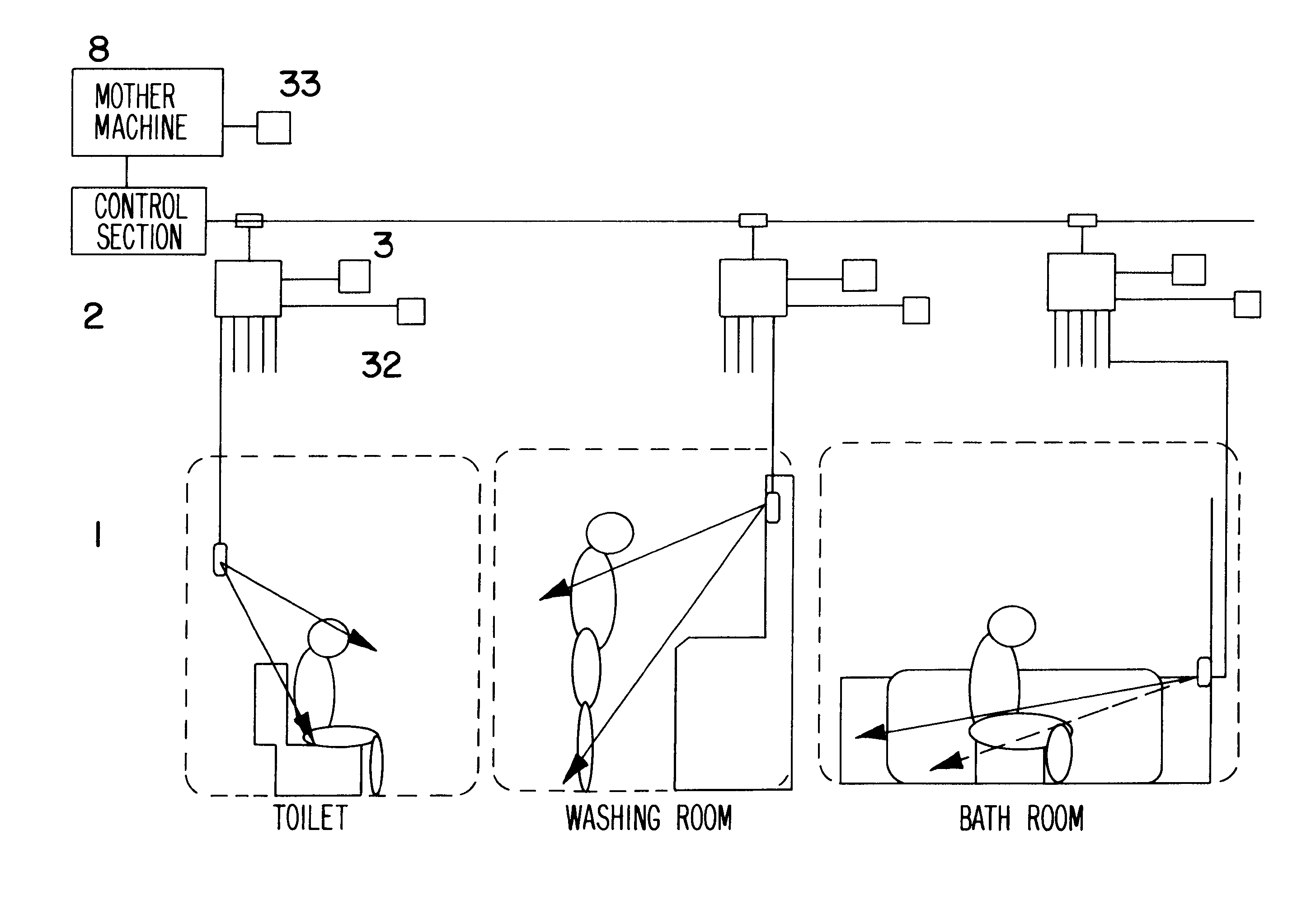
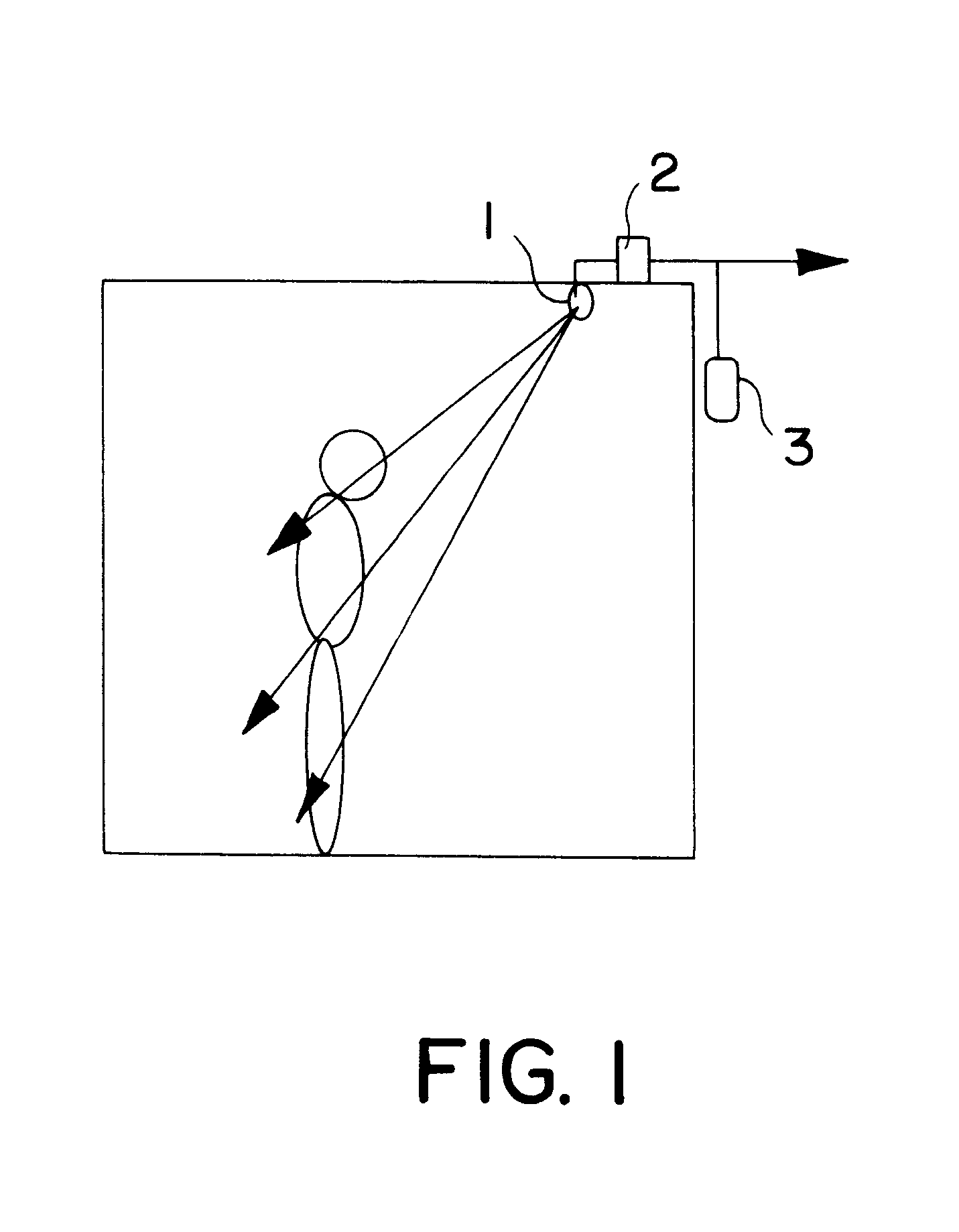
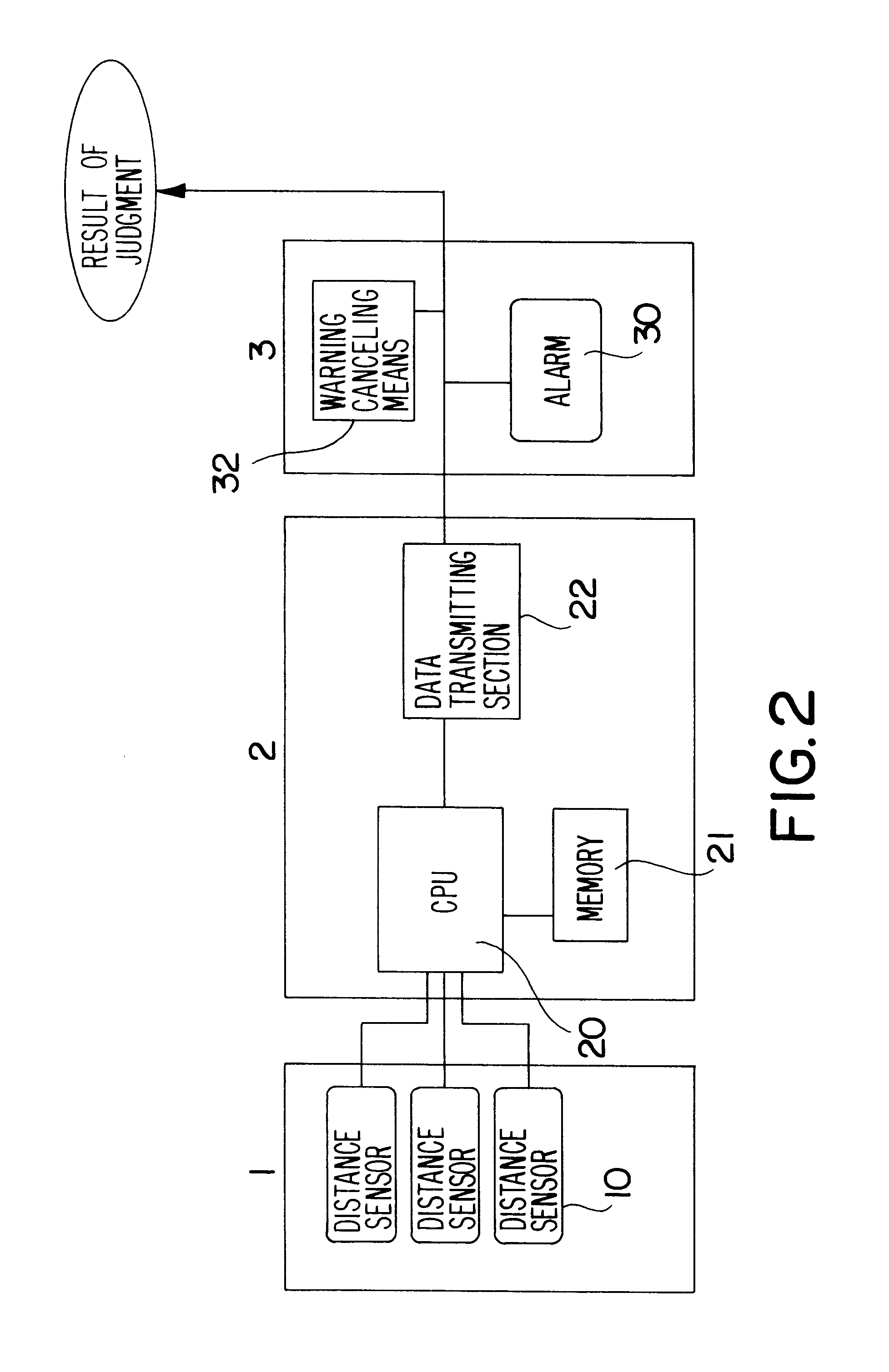
FIG. 1 and FIG. 2 are figures for describing a first embodiment of the present invention. In the figures, the signal obtained from detecting means 1 including a plurality of pieces of distance sensors 10 arranged on the ceiling or the side of an observing sector is used to judge the condition of a person in signal processing means 2. The signal processing means 2 comprises a CPU 20, a memory 21 containing the information to be the criterion, and a data transmitting section 22, and it judges the condition of a person by comparing the criterion and the input signal, and it transmits the judgment results to the outside by the data transmitting section 22.

For example, when it is judged that a person entered the observing sector and the person is still in the room after a certain time has elapsed, or when it is judged that the attitude has become ...

embodiment 2

(Embodiment 2)

A condition detecting system according to a second embodiment of the present invention will be described by referring to drawings.

FIG. 7 to FIG. 13 are figures for describing the second embodiment in a toilet of the present invention. In FIG. 7, (a) is a plan view seen from a ceiling, and (b) is a figure seen from the side. In FIG. 7, detecting means 1 including at least 3 pieces of distance sensors arranged on the side of a toilet which is an observing sector is provided, and it is set to be able to perform detection in the direction of a person 40 sitting on a toilet bowl 50 diagonally from the upper.

The processing method of the signal obtained from the detecting means 1 is similar to that in the Embodiment 1.

Now, in the case where a person entered the toilet and sat down on the toilet bowl, when it is judged by signals of 3 distance sensors that the person is still in the room after a certain time has elapsed, or when it is judged that the person is in an attitude w...

embodiment 3

(Embodiment 3)

A condition detecting system according to a third embodiment of the present invention will be described by referring to drawings.

FIG. 14 to FIG. 16 are figures describing the third embodiment in a washing room of the present invention. In FIG. 14, (a) is a plan view of a condition where a person is standing seen from the ceiling, and (b) is a figure seen from the side. FIG. 15 is a plan view of a condition where a person is lying on its side seen from the ceiling, and FIG. 16 is a figure of a condition where a person is sitting down seen from the side.

As shown in FIG. 14, detecting means 1 including at least 4 pieces of distance sensors arranged on the front upper portion of the washing room which is an observing sector is provided, and it is set to be able to detect a person 40 using a washing stand 60 diagonally from the upper. Each of the detecting directions 1 to 4 is set such that the detecting directions 2, 4 are set to detect the front upper and lower portions, ...


PUM


Abstract

Condition detecting system has a detecting device (1) including a plurality of pieces of distance sensors arranged at one corner of an observing sector such as a toilet, a judging device for judging the condition of a staying person in the observing sector on the basis of the information from the detecting device (1), a signal transmitting section for transmitting the results of judgment, and a warning device for issuing a warning on the basis of the signal from the signal transmitting section, and the plurality of pieces of distance sensors are set to perform detection in a plurality of different directions by using infrared ray beams.

Description

1. Field of the InventionThe present invention relates to a condition detecting system and method which performs detection of the condition of a person in an observing sector in a building or a house by using detecting means including a plurality of distance sensors.2. Related Art of the InventionPreviously, in order to detect the condition of a person in a specific area, it has been normally practiced that a picture in the space is measured by a CCD camera or an infrared ray camera and an observer directly performs observation through a monitoring screen, or that a person in the area is cut out of the picture and the recognition of the person is performed by a picture recognizing system.In the former case, it is necessary to watch the monitoring screen at all times, and it is difficult to cover a plurality of observing areas, and in the latter case, the system is considerably expensive, and the uses are limited. Furthermore, judgment is difficult as for the attitude of the person o...

Claims


Application Information

Patent Timeline
Patent Type & Authority Patents(United States)
IPC IPC(8): G01S17/00G01S17/02G01S17/87G01B11/24G01S17/04G01B11/245G01S17/86G01V9/00
CPCG01S17/026G01S17/87G01S17/023G08B21/0469G01S17/04G01S17/86
Inventor YOSHIIKE, NOBUYUKIMORINAKA, KATSUYATANAKA, SHINJI
Owner PANASONIC INTELLECTUAL PROPERTY CORP OF AMERICA
Why Eureka
Try Eureka