Hydropneumatic spring

a technology of hydraulic springs and spring rods, applied in the direction of vehicle springs, resilient suspensions, vibration dampers, etc., can solve the problems of high assembly costs, high components costs, and increased frictional force during the axial movement of piston rods

Inactive Publication Date: 2001-04-10
MANNESMANN SACHS AG
View PDF5 Cites 49 Cited by
  • Summary
  • Abstract
  • Description
  • Claims
  • Application Information

AI Technical Summary

Problems solved by technology

The complex structural design of this prior art spring cylinder entails high costs for the components and high costs for their assembly.
In particular, in the spring range in which the second spring energy store is shut off from the

Method used


Image

  • Hydropneumatic spring
  • Hydropneumatic spring
  • Hydropneumatic spring

Examples


Embodiment Construction

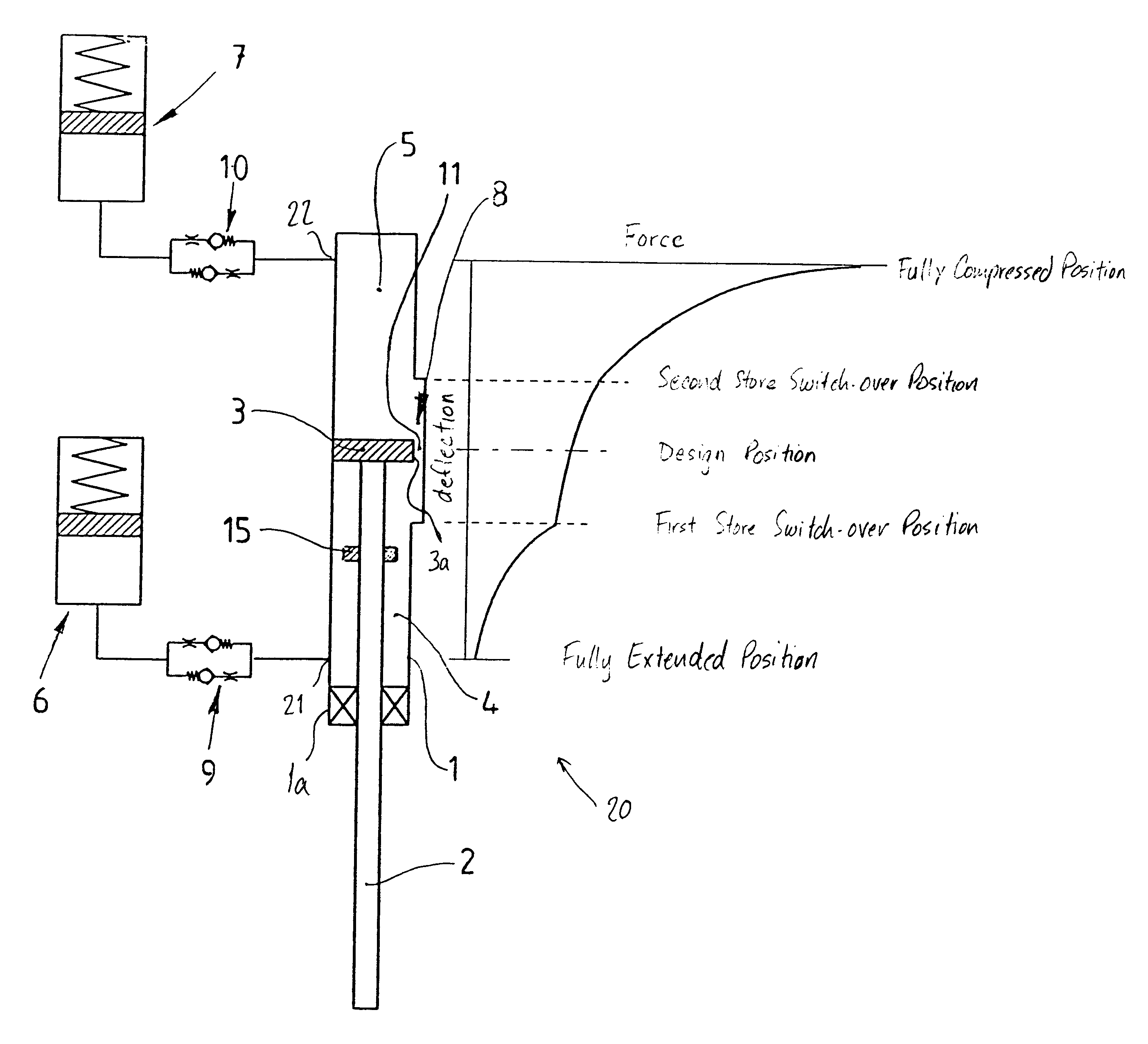
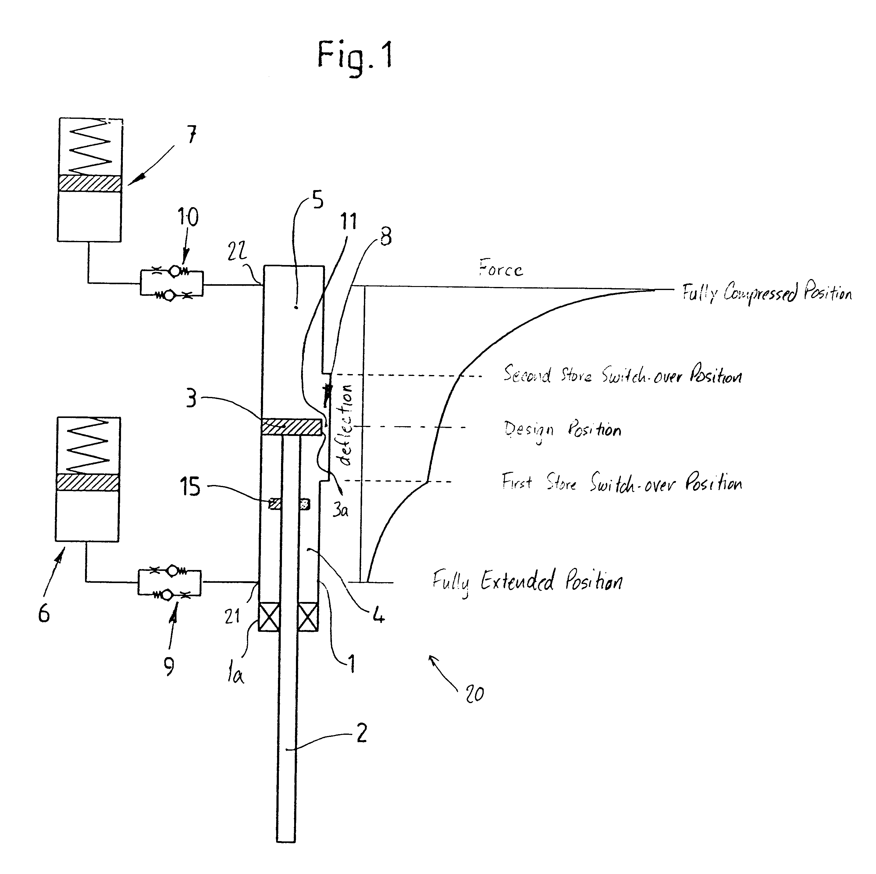
In a preferred embodiment, a hydropneumatic spring 20 shown in FIG. 1 is installed as a shock absorber in an articulated manner between a vehicle body and a wheel guiding part of a motor vehicle. However, the hydropneumatic spring 20 may be used with any device requiring a spring having deflection adjustable rates of change in spring force.

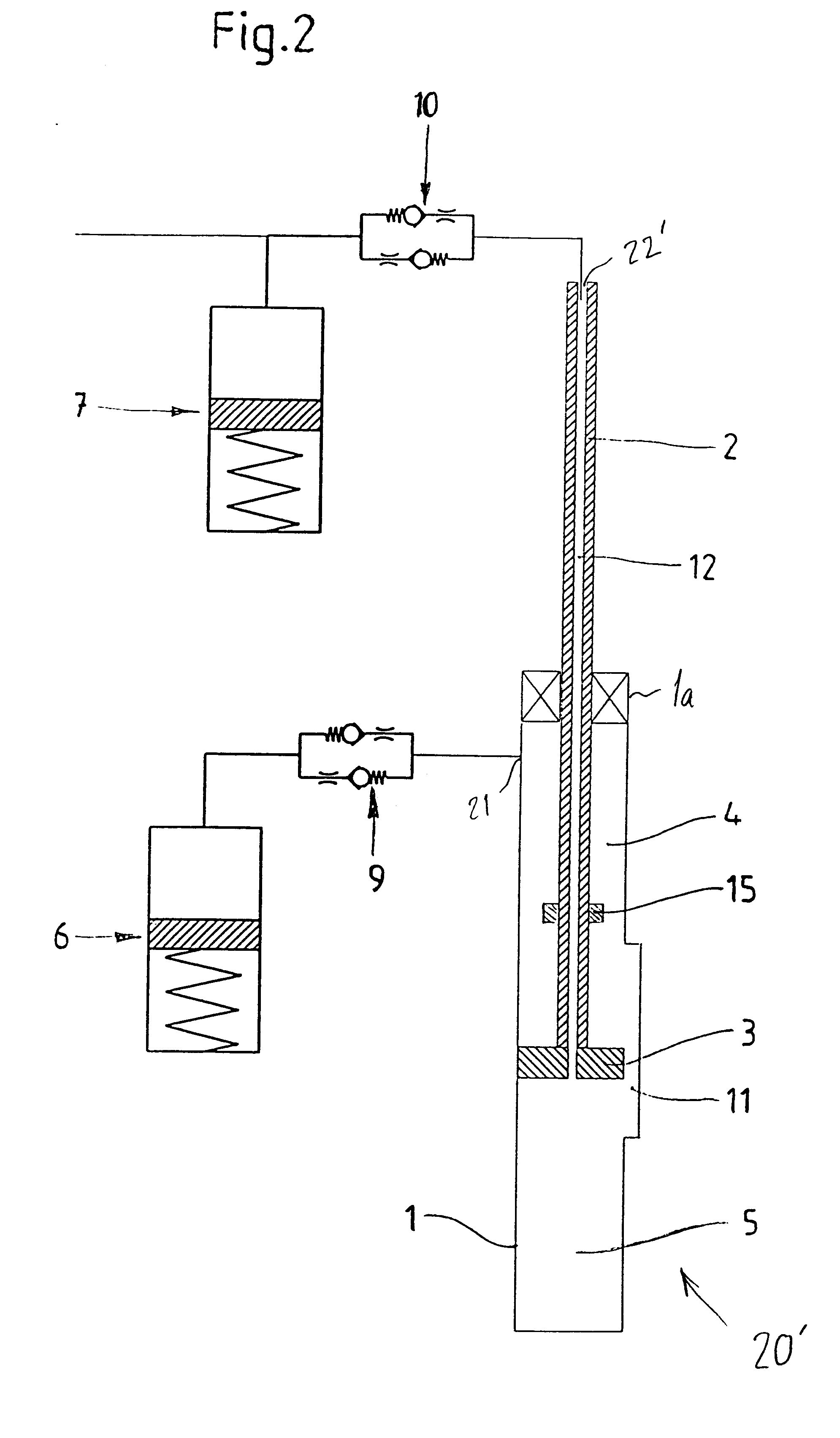
The hydropneumatic spring 20 has a cylinder 1 which is filled with a hydraulic fluid. An outwardly sealed piston rod 2 enters one end of the cylinder 1 through a piston rod guide la. The piston rod 2 is connected to a piston 3 that is guided in an axially movable manner in the cylinder 1. The interior space of the cylinder 1 is subdivided by the piston 3 into a first working chamber 4 on the piston rod side and a second working chamber 5 remote from the piston rod. A first spring energy store 6 is hydraulically connected via a valve device 9 and a connection 21 arranged in the cylinder 1 to the first working chamber 4 and a second spring energy st...


PUM


Abstract

A hydropneumatic spring, which is preferably articulately arranged between a vehicle body and a wheel guiding part in motor vehicles, has a fluid-filled cylinder which is entered by an outwardly sealed piston rod having a piston connected at the internal end. For altering spring force-deflection progressivity characteristic, a first working chamber of the cylinder is in constant hydraulic connection with a first spring energy store device and a second working chamber of the cylinder is in constant hydraulic connection with a second spring energy store device via a second valve device via a first valve device. In a mid spring deflection range, a second spring energy store device is connected via a second valve device and a bypass to the first spring energy store device. The bypass includes an axially extending channel arranged between the first working chamber and the second working chamber. The first and second working spaces are disconnected when the piston is not in the mid-deflection range and the channel does not bypass around the outer surface of the piston.

Description

1. Field of the InventionThe invention relates to a hydropneumatic spring, which is preferably arranged between a vehicle body and a wheel guiding part in a motor vehicle, having a fluid-filled cylinder which is entered by an outwardly sealed piston rod connected to a piston which divides the cylinder into first and second working chambers, the first working chamber of the cylinder being in hydraulic connection with a first spring energy store via a valve device for altering the force-deflection progressivity characteristic of the spring (rate of change in the spring force as the spring is deflected), the second working chamber of the cylinder being in hydraulic connection with a second spring energy store, and a bypass connecting the first working chamber to the second working chamber when the hydropneumatic spring is in a mid deflection range.2. Description of the Related ArtA prior art hydropneumatic spring having two spring energy stores is known from European reference EP 0 634...

Claims


Application Information

Patent Timeline
IPC IPC(8): F16F9/096F16F9/34F16F9/00F16F9/346B60G17/04B60G17/08F16F9/06
CPCB60G17/0416B60G17/08F16F9/065F16F9/346B60G2202/154
Inventor KUNKEL, ERNST-ACHIM
Owner MANNESMANN SACHS AG
Why Eureka
Try Eureka