Label for marking and remote detection of objects

a technology for labels and objects, applied in the field of labels for marking and remote detection of objects, can solve the problems of limited freedom of movement, inability to realize in a real situation, and the difficulty in implementing the method of housing the sensor elements in the labels,

Inactive Publication Date: 2001-04-17
KIESEWETTER LOTHAR +2
View PDF7 Cites 11 Cited by
  • Summary
  • Abstract
  • Description
  • Claims
  • Application Information

AI Technical Summary

Problems solved by technology

Common sources of disturbance are for instance the inevitable gravity force, limited freedom of movement due to the suspension or mounting of the sensor element in the label, frictional losses due to contact between the sensor element and the surrounding walls of the internal space of the label, etc.
In an ideal situation this can be regarded as a sensor element freely floating in vacuum, but this is impossible to realize in a real situation, obviously enough.
Previously known methods for housing the sensor elements in their labels suffer, among other things, from the following considerable disturbances and defects:
However, for manufacturing reasons it has proven difficult to locate this center point exactly, and even very small deviations from a correct center point will lead to beats in the resonance oscillations.
Considerable manufacturing costs are required in order to obtain a sufficiently precise center point mounting.
If the sensor element is mounted or supported at other points than the ones described above, undesired disturbances will be present in the resonance oscillations of the element.
However, at least one mounting point is still required for each sensor element, thereby causing problems as described above.
Furthermore, a non-planar sectional shape is disadvantageous in that the external height of the label becomes larger, since the sensor elements require more space in the vertical direction inside the label, and in that the sensor elements are difficult--and consequently expensive--to produce.
Such a label has the advantage of a small size, but on the other hand the label has a poor protection against external influences due to its softness.
Accordingly, the sensor element will be relatively well protected against external forces, but the internal forces--due to the friction--in the cavity may severely reduce the sensor function of the element.
In addition this solution does not seem cost efficient.

Method used


Image

  • Label for marking and remote detection of objects
  • Label for marking and remote detection of objects
  • Label for marking and remote detection of objects

Examples


Embodiment Construction

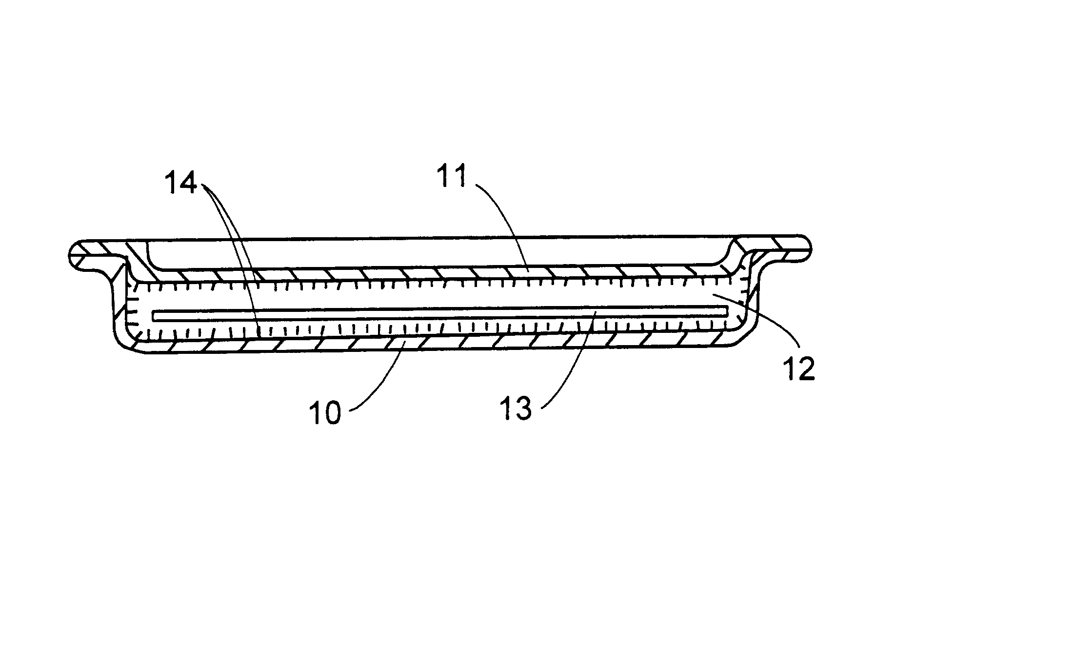
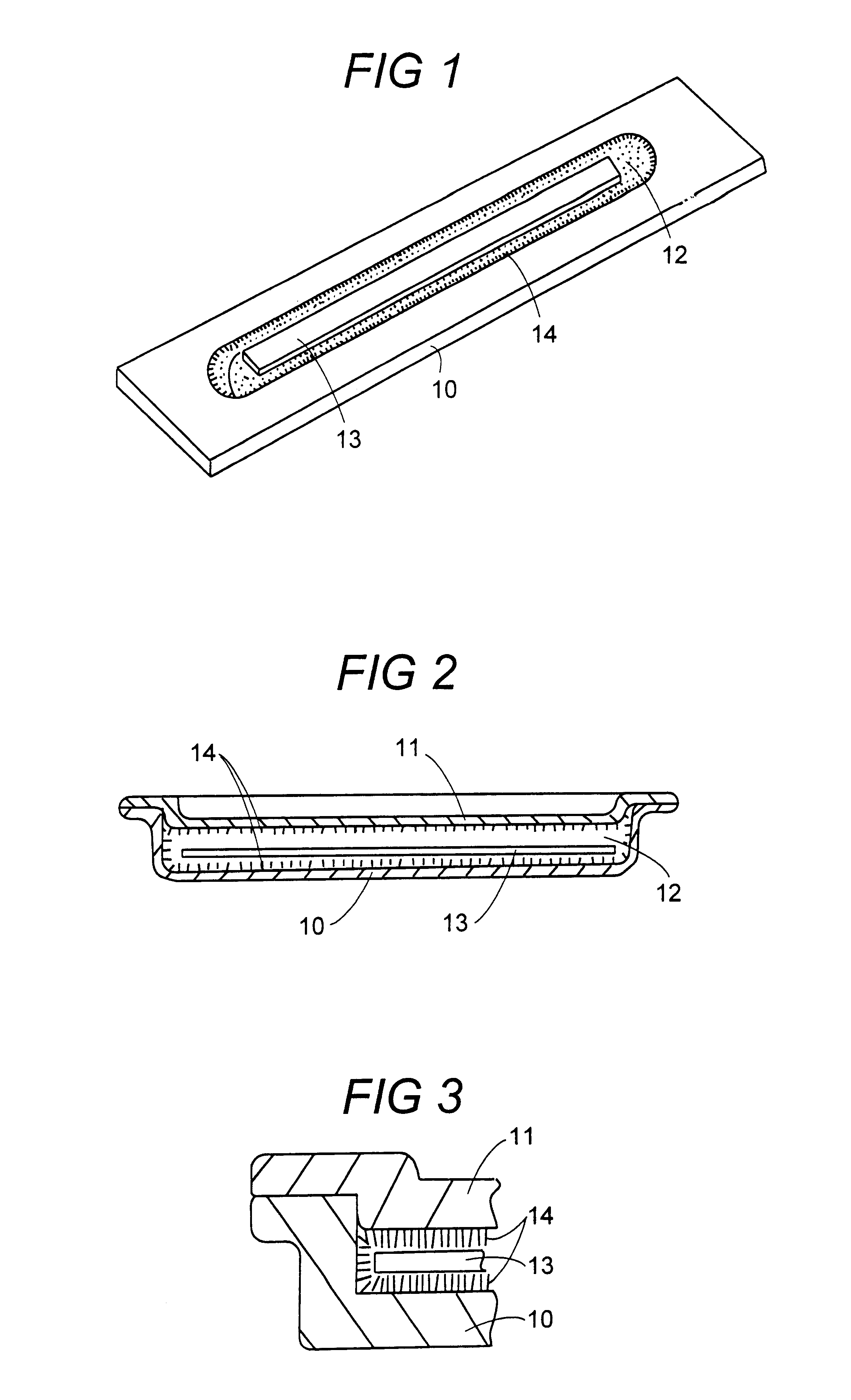
A label acccording to a preferred embodiment of the invention comprises a housing with a lower portion 10 and an upper portion or cover 11, both of which are preferably made from plastics or similar material, which lacks magnetic properties and which may be massproduced at a low cost, as disclosed in FIGS. 1 and 2. The label is arranged to be attached to the intended object--such as a shop article, a piece of furniture or a piece of clothing--by for instance gluing, mounting or sewing. A cavity 12 is formed in the internal portion of the label housing 10, 11 by a longitudinal recess in the lower portion 10. On the inside of the cover 11 a corresponding protruding portion is formed, which follows the recess in the lower portion 10. A space is formed between the recess and the protruding portion, the volume of which is large enough for receiving and housing a sensor element 13, as described below.

The sensor element 13 is formed as an elongated ribbon of amorphous magneto-elastical mat...


PUM


Abstract

A label for marking and remote detection of objects has a capsular housing (10, 11) of a material, which in non-magnetic, electrically non-conductive as well as resistant against external influence, the housing consisting of a lower portion (10) and a cover (11), between which a cavity (12) is formed, and at least one elongated sensor element (13) arranged in the cavity (12), the sensor element being made from an amorphous magneto-elastic material with high magneto-mechanical coupling. On all its interior surfaces facing the cavity (12), the housing (10, 11) is provided with fine bristles or fibers (14), the number, length and density of which have been selected for receiving the sensor element (13) in a way, such that the sensor element (13) when resonating, will maintain its straightness and will be allowed to oscillate in the longitudinal direction thereof essentially free from losses, with no harmful influence from bending or torsional forces, and with no risk of losing energy due to friction or contact with the inside of the housing (10, 11).

Description

The present invention relates to a label for marking and remote detection of objects, comprising a capsular housing of a material, which is non-magnetic, electrically non-conductive and resistant against external influences, the housing comprising a lower portion and a cover, between which a cavity is formed, and at least one elongated sensor element, which is arranged in the cavity and consists of amorphous magneto-elastical material with high magneto-mechanical coupling.DESCRIPTION OF THE PRIOR ARTLabels of the kind described above are disclosed in for instance the European patent publications EP-A2-0 093 281 and EP-A2-0 096 182, in the American patent publication U.S. Pat. No. 4,647,917, in the international patent publication WO88 / 01427 and in the published Swedish patent application 9402943-6. According to these publications the labels are provided with an internal space, in which one sensor element or a plurality of sensor elements is / are arranged.Each sensor element has the s...

Claims


Application Information

Patent Timeline
Patent Type & Authority Patents(United States)
IPC IPC(8): G08B13/24H01L41/00H01L41/12
CPCG08B13/2408G08B13/2434H01L41/12H10N35/00
Inventor KIESEWETTER, LOTHARZILLESSEN, HARALDTYREN, CARL
Owner KIESEWETTER LOTHAR
Why Eureka
Try Eureka