Baffle for a liquid tank

a liquid tank and baffling technology, applied in the field of baffling, can solve problems such as catastrophic failure of the tank

Inactive Publication Date: 2001-04-24
BAE SYSTEMS PLC
View PDF12 Cites 15 Cited by
  • Summary
  • Abstract
  • Description
  • Claims
  • Application Information

AI Technical Summary

Problems solved by technology

The shock waves and resulting hydraulic ram pressure in the liquid, combined with the penetration damage from the projectile, ran cause damage to the tank structure and frequently are the cause of catastrophic failure of the tank.

Method used


Image

  • Baffle for a liquid tank
  • Baffle for a liquid tank
  • Baffle for a liquid tank

Examples


Embodiment Construction

For a better understanding of the present invention, and to show how the same may be carried into effect, reference will now be made, by way of example, to the accompanying drawings in which:

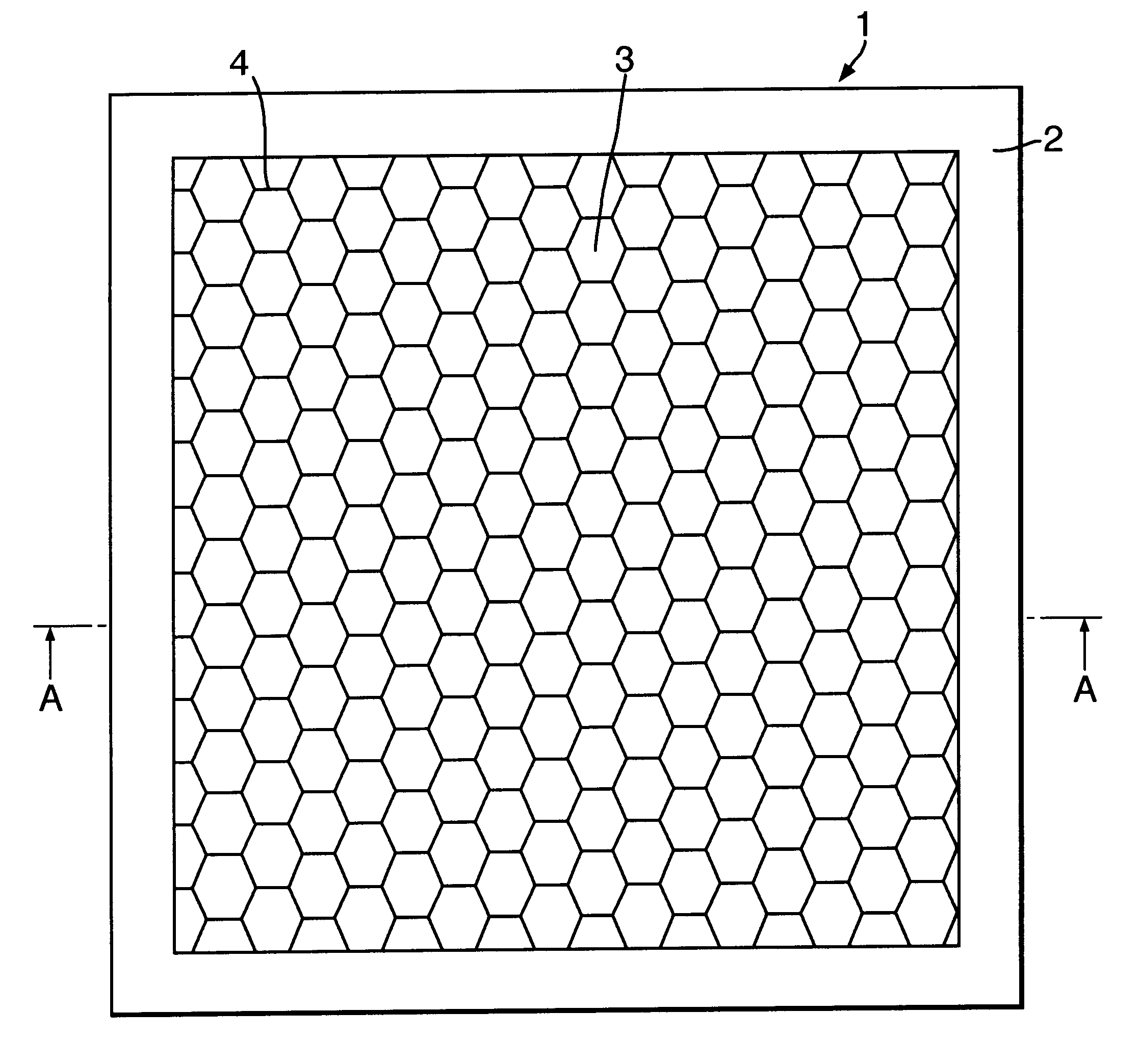
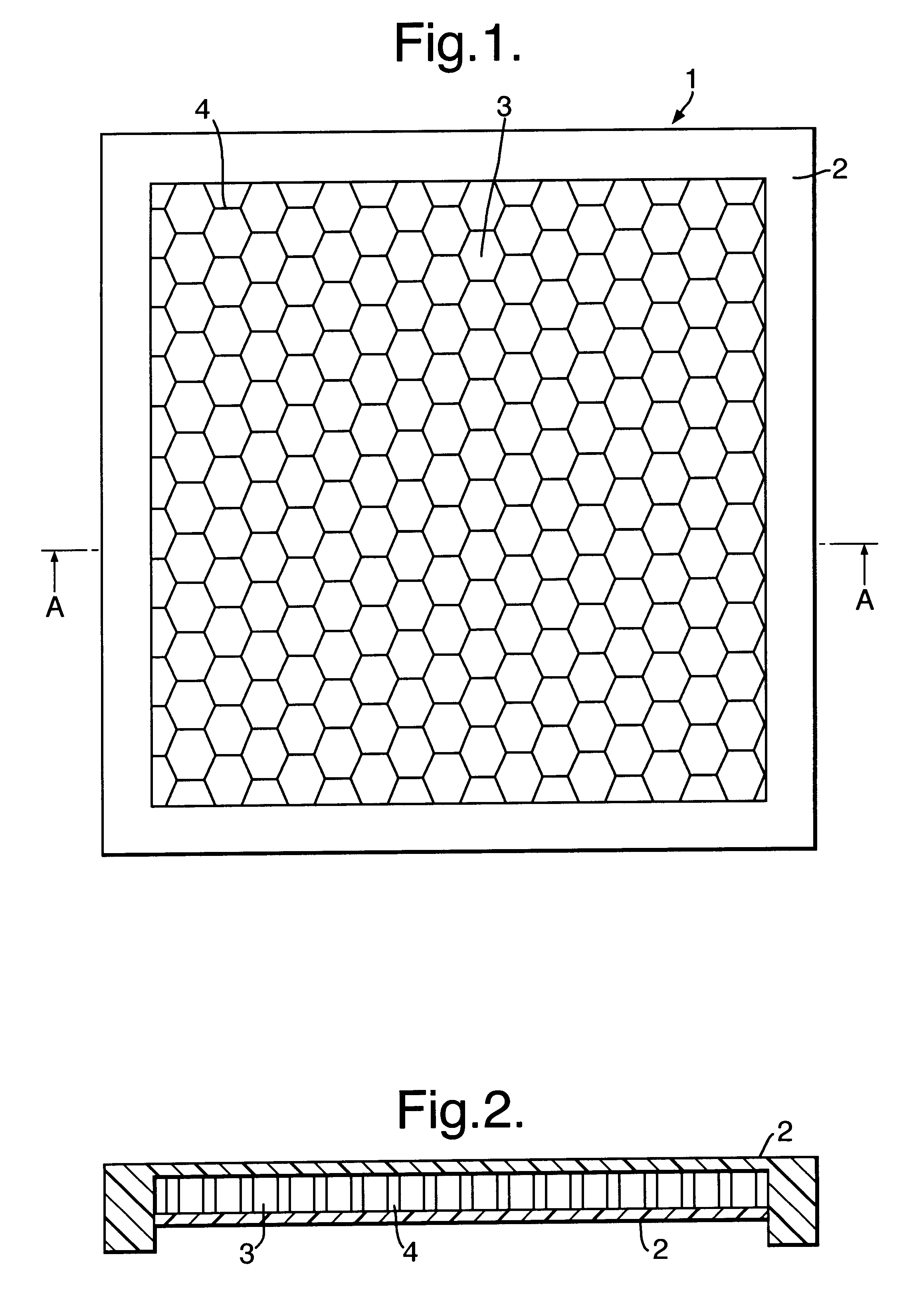
FIG. 1 is a plan view of a baffle according to one embodiment of the present invention,

FIG. 2 is a cross sectional view through the baffle of FIG. 1 taken on the line A--A in FIG. 1,

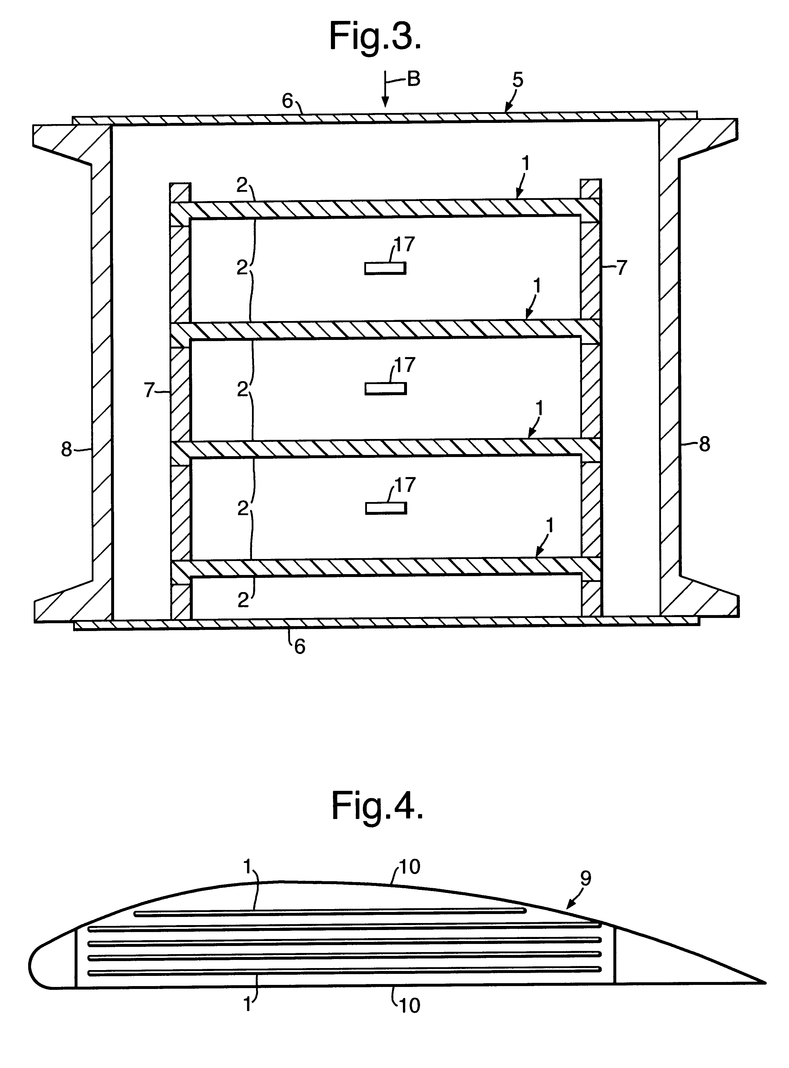
FIG. 3 is a vertical cross sectional view through a tank according to a further embodiment of the present invention shown including baffles according to the present invention,

FIG. 4 is a cross sectional diagrammatic view through a wing tank according to a further embodiment of the present invention,

FIG. 5 is a graphical plot of the shock wave pressure against time for a high speed projectile impact into a water filled tank at a velocity of 2009 meters per second,

FIG. 6 is a graphical plot of shock wave pressure against time for a high speed projectile impact into a water filled tank according to the present invention...


PUM


Abstract

A baffle (1) for reducing hydraulic ram pressure in a liquid in a tank (5,9) in which it is located resulting from impact of a projectile on an external surface (6,10) of the tank, includes at least two outer walls (2) spaced apart to define therebetween at least one cavity (3) and a compressible gas or gaseous mixture at reduced, atmospheric or enhanced pressure contained in the cavity (3). The baffle outer walls (2) are sufficiently strong to withstand the pressure of the gas or gaseous material contained in the cavity (3) are sufficiently strong to resist the hydrostatic pressure of liquid in a tank (5,9), when the baffle (1) is located in the liquid in the tank (5,9), and are spaced apart by an amount sufficient to provide the cavity with a volume sufficient to allow a shock wave or waves in the liquid resulting from compression of the liquid by impact of a projectile on the tank external surface (6) to be reduced by expansion of the compressed liquid into the cavity volume. The gas or gaseous mixture has a density sufficiently different from the density of the liquid to provide substantially total reflection within the baffle (1) of the shock wave or waves impinging on the baffle.

Description

1. Field of the InventionThis invention relates to a baffle for location in tank for liquid, which baffle is operable to reduce hydraulic ram pressure in the liquid resulting from impact of a projectile with an external surface of the tank, and to a tank containing such a baffle.2. Discussion of Prior ArtA high speed projectile on impact with and penetration into a liquid containing tank generates very high pressure in the liquid which propagates as intense shock waves producing hydraulic ram pressure in the liquid. The shock waves and resulting hydraulic ram pressure in the liquid, combined with the penetration damage from the projectile, ran cause damage to the tank structure and frequently are the cause of catastrophic failure of the tank. The hydraulic ram pressure pulses are intense but of short duration which propagate through the liquid in the tank.There is thus a need for means for reducing hydraulic ram pressure in the liquid in such a tank and for a generally improved tank...

Claims


Application Information

Patent Timeline
Patent Type & Authority Patents(United States)
IPC IPC(8): B64D37/00B64D37/08B64D37/32B65D90/52
CPCB64D37/08B64D37/32B64D2037/325
Inventor TOWNSEND, DAVIDZAVTRAK, SERGUEI TMCEWEN, ROGNVALD S
Owner BAE SYSTEMS PLC
Why Eureka
Try Eureka