
Support device

a technology of supporting device and support plate, which is applied in the field of support plate, can solve the problems of not taking into account the substantial unevenness caused by prior art, harmful to patients that are disabled, and tendencies to bedsores, etc., and achieves the effect of convenient and functional us

Inactive Publication Date: 2001-05-01
ANSLIN JYRKI
View PDF23 Cites 21 Cited by
  • Summary
  • Abstract
  • Description
  • Claims
  • Application Information

AI Technical Summary

Benefits of technology

One object of the present invention is to provide a support device which, in an inflated state, fully or partly lifts a person resting thereupon and which forms a surface which is generally free from unevennesses which would cause discomfort or hurt a person resting thereupon as the support device is positioned onto a base member such as a mattress, a bunk or a bed. Another object of the invention is to provide a cheap and functional alternative to support devices of prior art. This object is obtained by a support device of the type initially defined, which is characterized in that the inflatable portion comprises a lateral projection provided to project beyond a lateral edge of the base member and at which said opening is arranged.
Thereby the maintenance of the hygiene of a person resting on the support device is substantially facilitated in the case where said person is totally or partly unable of moving himself or herself, which is often the case for patients taken care of by the medical service. Hereby, one assisting person is enough in order to position the patient above the bowl-shaped element, or so called basin, into which the patient is to relieve himself or herself, which is an advantage. Also afterwards, when the bowl-shaped element has been removed from its operative position, the embodiment is advantageous in that a cleaning of the patient may take place through the recess, and the patient does not need to be further moved in order to be cleaned.
Thereby, a particular advantage is obtained as a decoppling of the support device from the inflation medium may take place after the inflatable portion has been brought to its inflated state, and as the base member, often constituted by a bed with wheels in a hospital, may be removed from the source of the inflation medium while, at the same time, the inflated state is maintained.
Thereby, particularly the risk of obtaining to high pressure in the inflatable portion during the inflation thereof is avoided. A too high pressure will otherwise, in the worst case, result in a bursting of the inflatable portion, which, of course, is not desirable. Thanks to the evacuation valve being arranged at the lateral projection, the valve may be of significant dimension, which may be advantageous when a rapid evacuation is requested.
Thereby, a very simple construction is obtained, which, in principle, is only comprised by the inflatable portion and a band or a surface onto which it is attached.
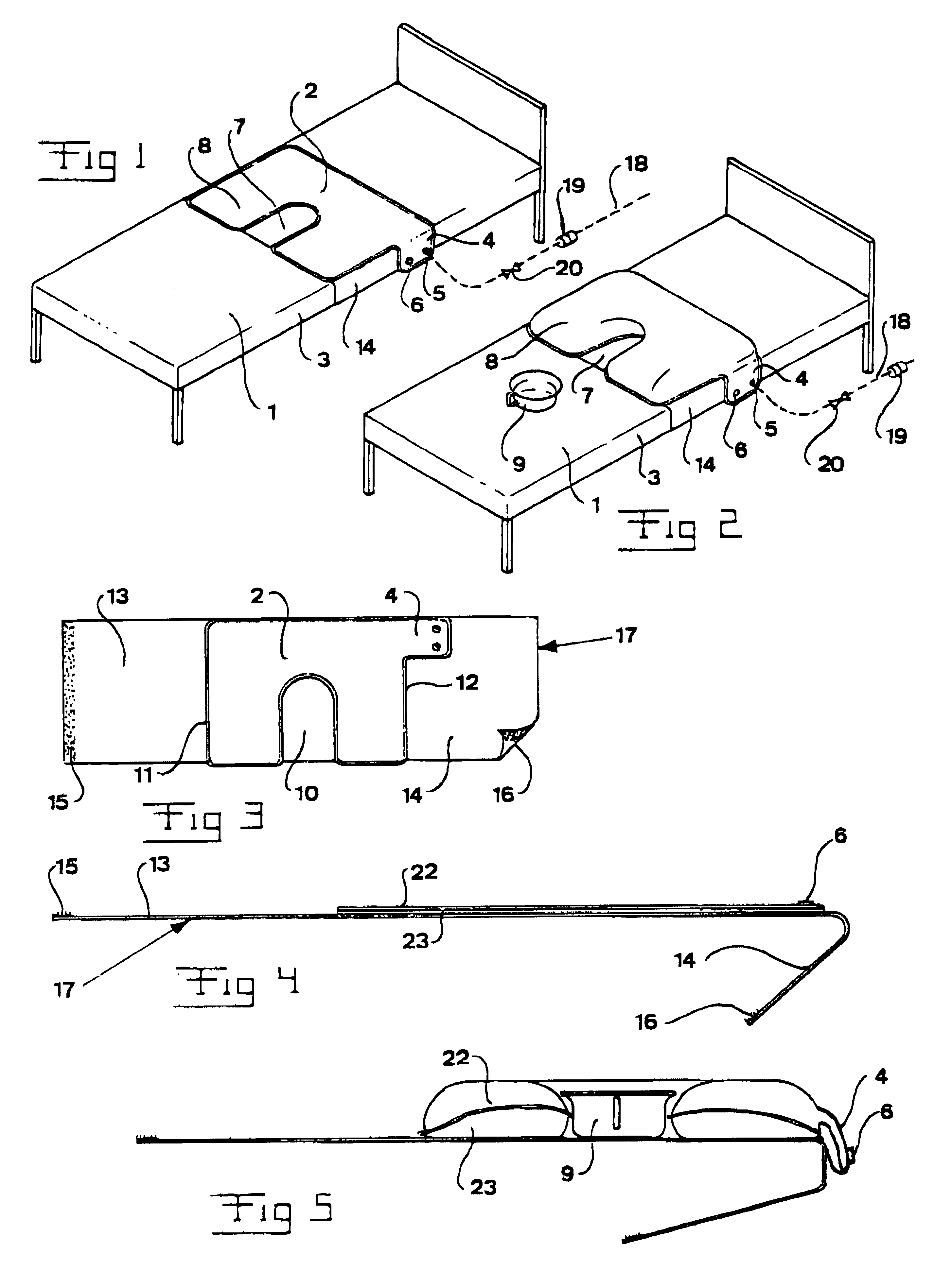
Surprisingly, such a very simple construction appears to be enough in order to accomplish those shapes that are desired for the inflatable portion in its evacuated state as well as in its inflated state. The consumption of material for the manufacture of the inflatable portion becomes minimal, as well as the total seam length required for the joining of this portion. The maximum thickness of the portion in the evacuated state may also be minimized as thee are only two layers needed.

Problems solved by technology

However, prior art does not take into consideration the substantial unevenness caused by the inlet and outlet openings respectively and valves possibly arranged at said openings.
Thereby, the patient may lay upon these unevennesses, which might me found uncomfortable by patients in general and which might be harmful to patients that are disabled or have tendencies towards bedsores.

Method used


Image

  • Support device
  • Support device

Examples


Embodiment Construction

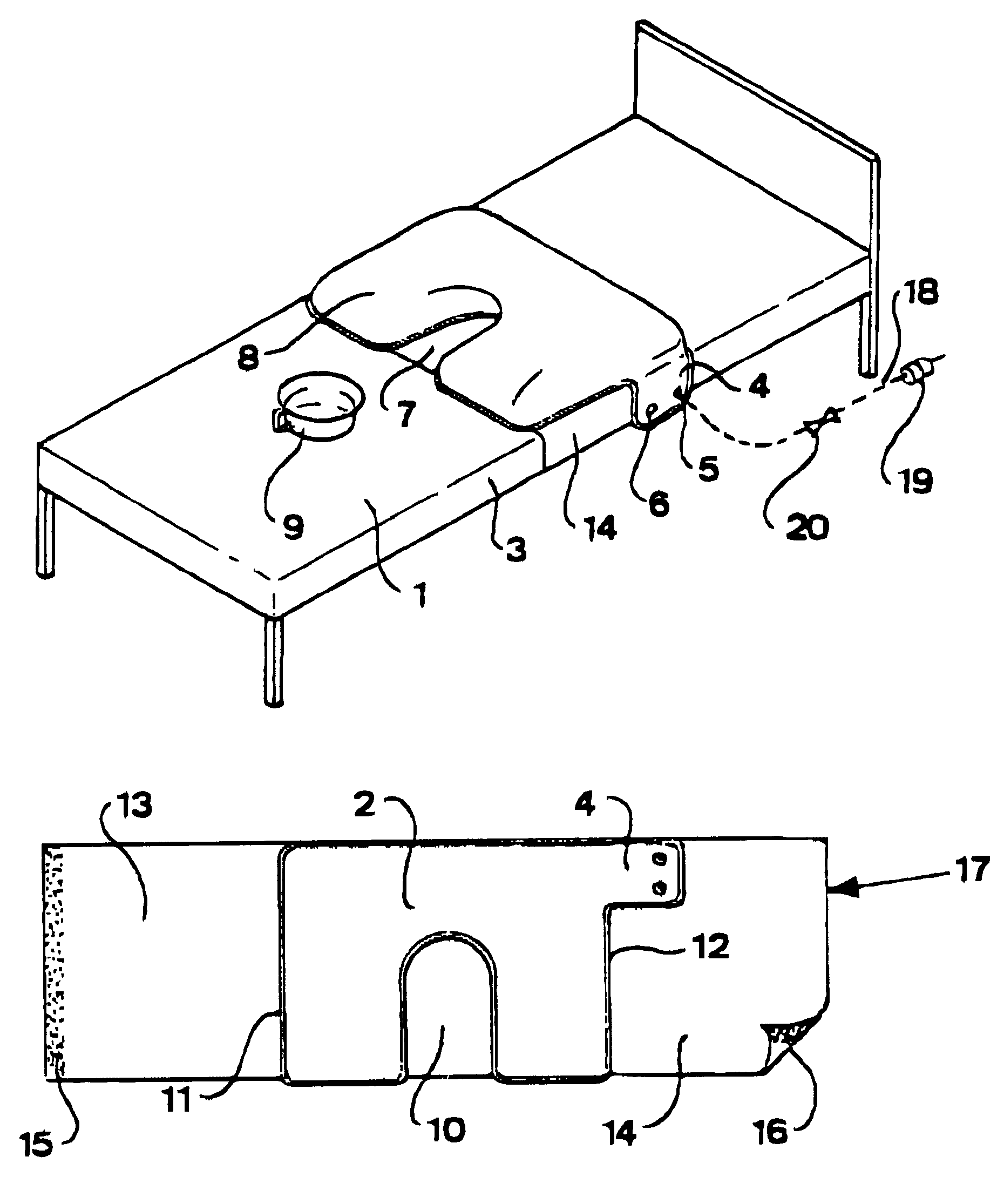
In the figures, an embodiment of the support device according to the invention is shown, said device being provided to be arranged on a base member 1, which might be a mattress, a bunk or, as in this case, a bed. The support device comprises an inflatable portion 2, provided to be in an inflated state in order to lift a person resting on the inflatable portion 2.

The inflatable portion 2 is provided to extend to at least one lateral edge 3 of the base member 1. At this end of the inflatable portion, it comprises a lateral projection 4 provided to project beyond the lateral edge 3 of the base member 1 and at which an inlet opening 5 and an outlet opening 6 are arranged. The lateral projection 4 extends, amongst other, from considerations of space, only along a part of the end or side of the inflatable portion 2 from which it projects. However, it could as well be arranged along a greater part or along all of this side.

In practice, the lateral projection 4 forms a part of the inflatabl...


PUM


Abstract

A support device provided to be arranged on a base member (1) such as a mattress, a bunk or a bed, and comprising an inflatable portion (2) which is arranged to be in an inflated state in order to lift a person resting upon the inflatable portion (2), the inflatable portion (2) comprising an inlet opening (5) and an outlet opening (6) for the supply and evacuation respectively of an inflation medium. The inflatable portion (2) comprises a lateral projection (4) provided to project beyond a lateral edge (3) of the base member (1) and at which the inlet opening (5) and the outlet opening (6) are arranged.

Description

THE BACKGROUND OF THE INVENTION AND PRIOR ARTThe present invention relates to a support device provided to be arranged onto a base member such as a mattress, a bunk or a bed, and comprising an inflatable portion provided to be in an inflated state in order to lift a person resting upon the inflatable portion, the inflatable portion comprising at least one opening for the supply and evacuation of an inflation medium.According to prior art, a plurality of such support devices are known, these particularly being arranged to permit the insertion of a bowl or the like below a person resting on the support device in order to permit said person to relieve himself or herself by means of said bowl while being supported by the inflatable portion on which the person may lay or sit. In particular, such devices are provided to be used in the medical service where the persons being treated often have substantial difficulties in moving themselves in order to relieve themselves, and where, accordin...

Claims


Application Information

Patent Timeline
IPC IPC(8): A61G7/10
CPCA61G7/1009A61G7/1021A61G2200/32A61G2200/34
Inventor ANSLIN, JYRKI
Owner ANSLIN JYRKI
Learn More