Method of manufacturing ink jet head

a manufacturing method and printer technology, applied in the field of ink jet type printers, can solve the problems of reducing rigidity, difficult to form thin piezoelectric elements, and restricting the application of this principl

Inactive Publication Date: 2001-05-01
FUJIFILM HLDG CORP
View PDF25 Cites 51 Cited by
  • Summary
  • Abstract
  • Description
  • Claims
  • Application Information

AI Technical Summary

Problems solved by technology

However, application of this principle is restricted for the following several reasons.
However, it is difficult to form a thin piezoelectric element.
However, the rigidity is lowered, and it becomes impossible to generate a high pressure, that is, it is impossible to provide a sufficiently high ink ejecting pressure.
However, since restricted by the construction, only one surface of the piezoelectric element is driven.
Therefore, ejection of ink deviates due to the unbalance of the activating area of the piezoelectric element.
However, when one pressure chamber is strongly joined to the compound plate-shaped member of the other pressure chamber which is adjacent to the above pressure chamber, ink ejection from one pressure chamber is affected by the deformation of the compound plate-shaped member of the other pressure chamber which is adjacent to the above pressure chamber.
In this structure, when the restriction of the piezoelectric element on the side which is not fixed is too strong or weak, the efficiency of deformation is deteriorated.

Method used


Image

  • Method of manufacturing ink jet head
  • Method of manufacturing ink jet head
  • Method of manufacturing ink jet head

Examples


Embodiment Construction

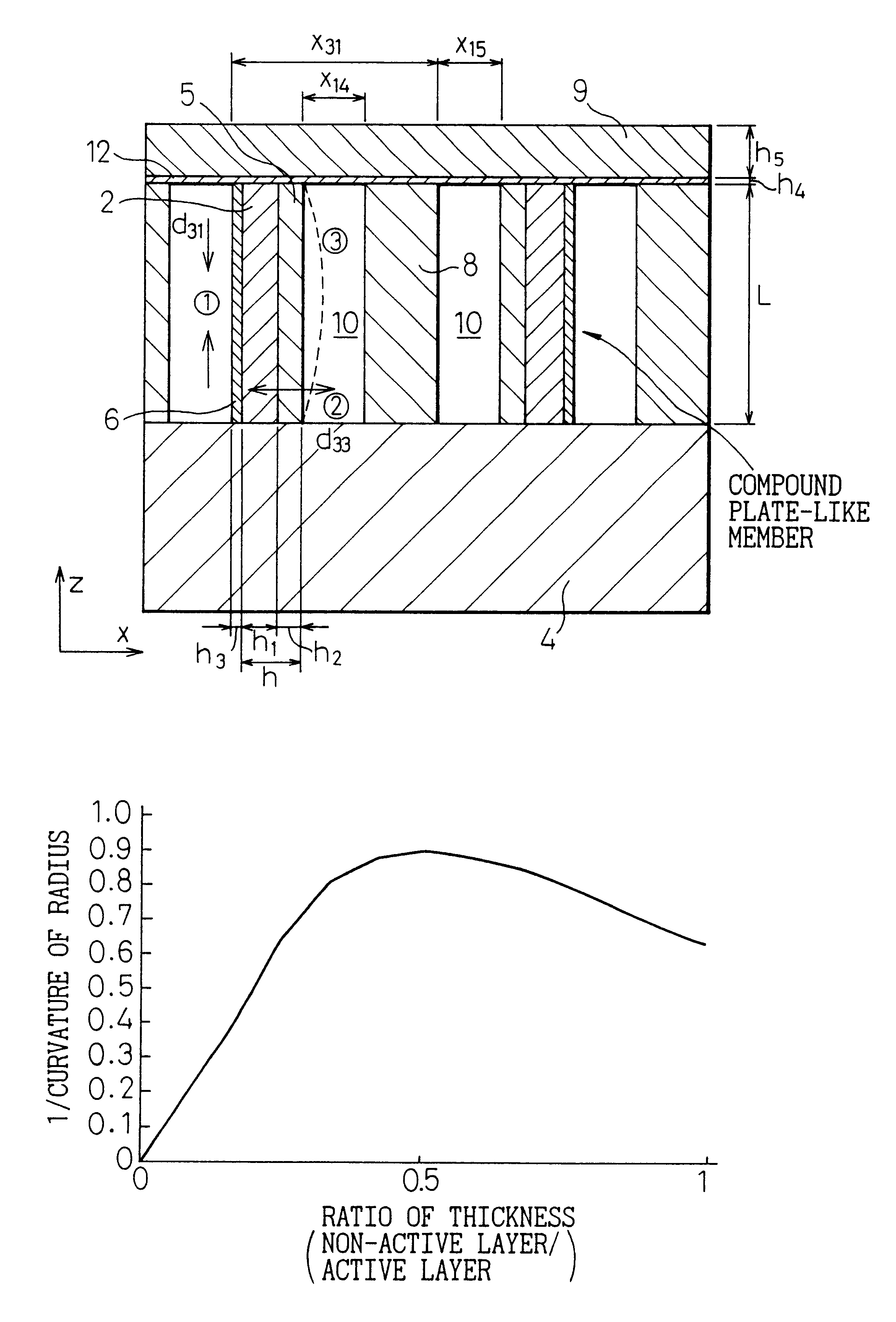
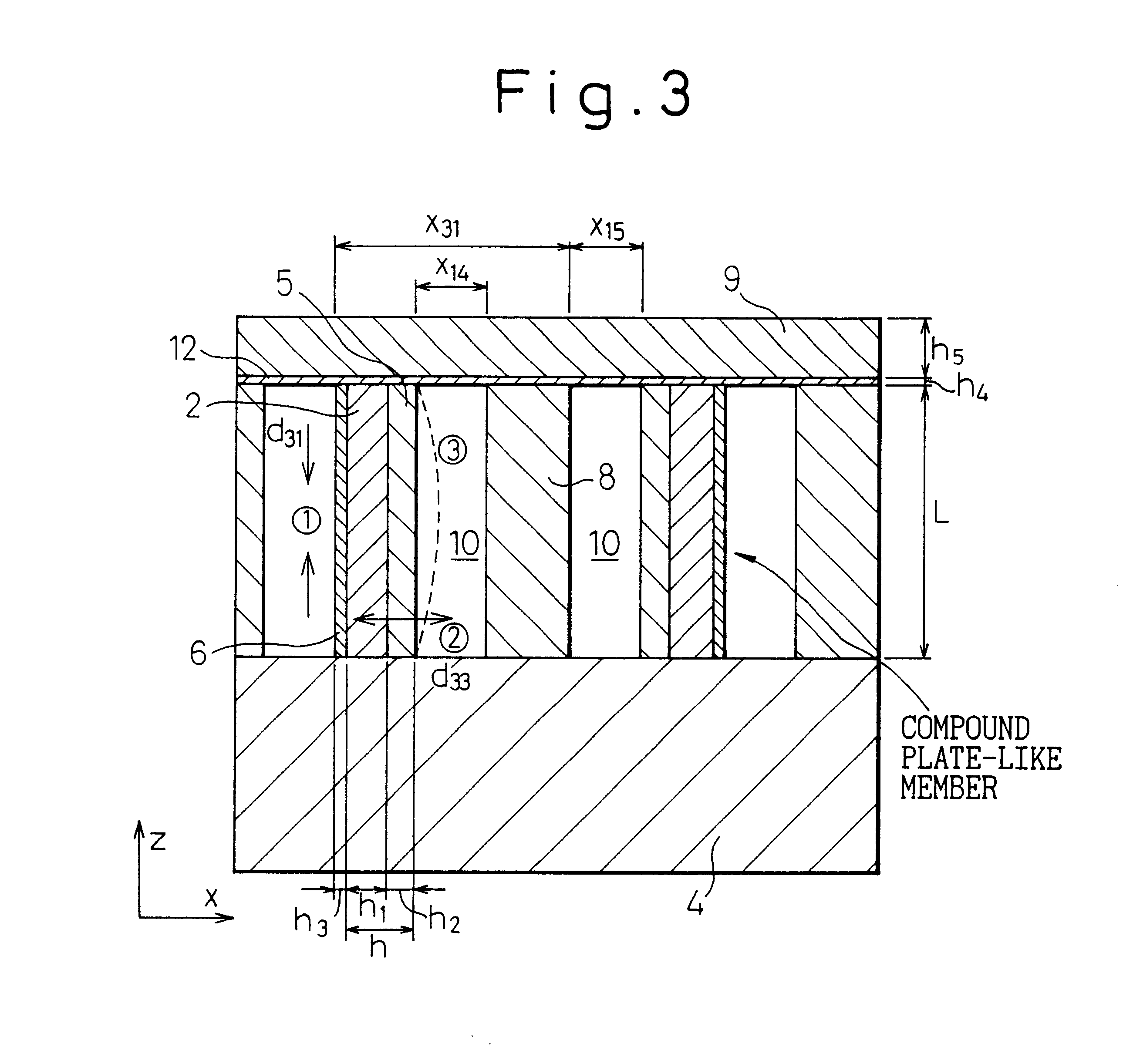
FIG. 3 is a cross-sectional view showing a primary portion (pressure chamber) of the first example of the ink jet head of the present invention.

As illustrated in FIG. 3, there are provided a large number of pressure chambers 10 in the direction x. Although not illustrated in FIG. 3, each pressure chamber is communicated with a nozzle through which ink is ejected from the pressure chamber 10, and also communicated with an ink feed port through which ink is fed into this pressure chamber. There is provided a compound plate-shaped member 1 by which one wall of the pressure chamber is defined. The compound plate-shaped member 1 is composed in such a manner that conductors (unactivated layers) 5, 6, which are used as electrodes, are joined onto both sides of a piezoelectric element (activated layer) 2.

This compound plate-shaped member 1 defines one wall of the pressure chamber 10. The direction of polarization of the piezoelectric element 2 is the same as the direction of x. The directio...


PUM

PropertyMeasurementUnit
thicknessaaaaaaaaaa
displacement volumeaaaaaaaaaa
voltageaaaaaaaaaa

Abstract

A method of manufacturing an ink jet head includes the following steps, wherein the ink jet head is provided with a plurality of pressure chambers arranged continuously, ink feed means for feeding ink into these pressure chambers, and ink ejecting means for ejecting ink from each pressure chamber via a nozzle, so as to feed and eject ink by a change in volume of each pressure chamber. First, a first metallic film is formed on both surfaces of at least one wall composing the pressure chamber perpendicular to an arranging direction of the plurality of pressure chambers, wherein the at least one wall is one wall of a piezoelectric element deformed when a voltage is impressed. Then, the first metallic film formed on one of the both surfaces of at lest one wall is removed to form an exposed surface of the wall of the piezoelectric element. Thereafter, a second metallic film is formed on the exposed surface, whereby metallic films, thicknesses of which are different from each other, are formed on the both surfaces of at least one wall of the piezoelectric element.

Description

1. Field of the InventionThe present invention relates to an ink jet type printer used for a recording apparatus such as a printer, a copier or facsimile to record characters and images. More particularly, the present invention relates to an ink jet head in which the deformation of a piezoelectric element is used for a drive source to drive an ink jet pump.Recently, printers are indispensable for attaining office automation. Moreover, printers are coming widely into private use. As a printer for private use, the ink jet type printer attracts the attention of users because, compared with a wire drive type printer in which printing is conducted on a sheet of paper by pressing a wire against a platen via an ink ribbon, the ink jet type printer in which an ink jet head is used is advantageous in that: it makes little noise; the printing speed is relatively high; and the printing cost per sheet of paper is low.2. Description of the Related ArtA pump to eject liquid by using the deformati...

Claims


Application Information

Patent Timeline
Patent Type & Authority Patents(United States)
IPC IPC(8): B41J2/14B41J2/16B41J2/045B41J2/055
CPCB41J2/14209B41J2/1609B41J2/1623B41J2/1632B41J2/1643B41J2/1642Y10T29/49165Y10T29/42Y10T29/49401B41J2/045
Inventor OIKAWA, KOICHIKODAMA, JUNIWAISHI, AKIRAKATO, MASAYUKISHINGAI, TOMOHISAYOSHIDA, YUJIOGAWA, KAZUKIYABU, RYOSUKEMIZOBUCHI, ISAONAGAI, MASAHIRO
Owner FUJIFILM HLDG CORP
Why Eureka
Try Eureka