Modular cladding element

Inactive Publication Date: 2001-05-08
L B PLASTICS
View PDF19 Cites 89 Cited by
  • Summary
  • Abstract
  • Description
  • Claims
  • Application Information

AI Technical Summary

Benefits of technology

It is another object of the invention to provide a cladding element which, when assembled with other elements, creates a surface that is generally maintenance free.
It

Problems solved by technology

A problem arises when it becomes necessary or desirable to position the elements such that the same type of fasteners of adjac

Method used


Image

  • Modular cladding element
  • Modular cladding element
  • Modular cladding element

Examples


Embodiment Construction

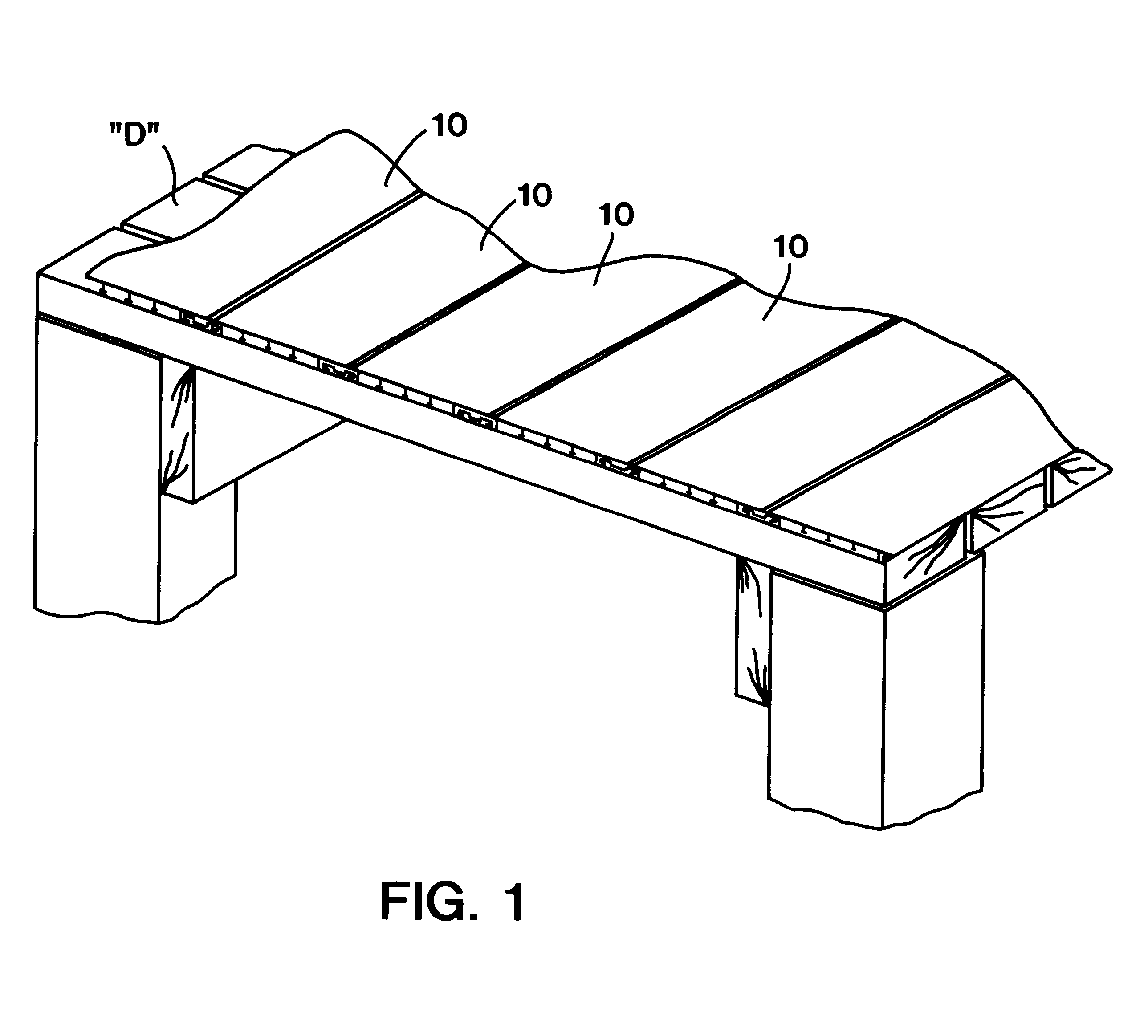
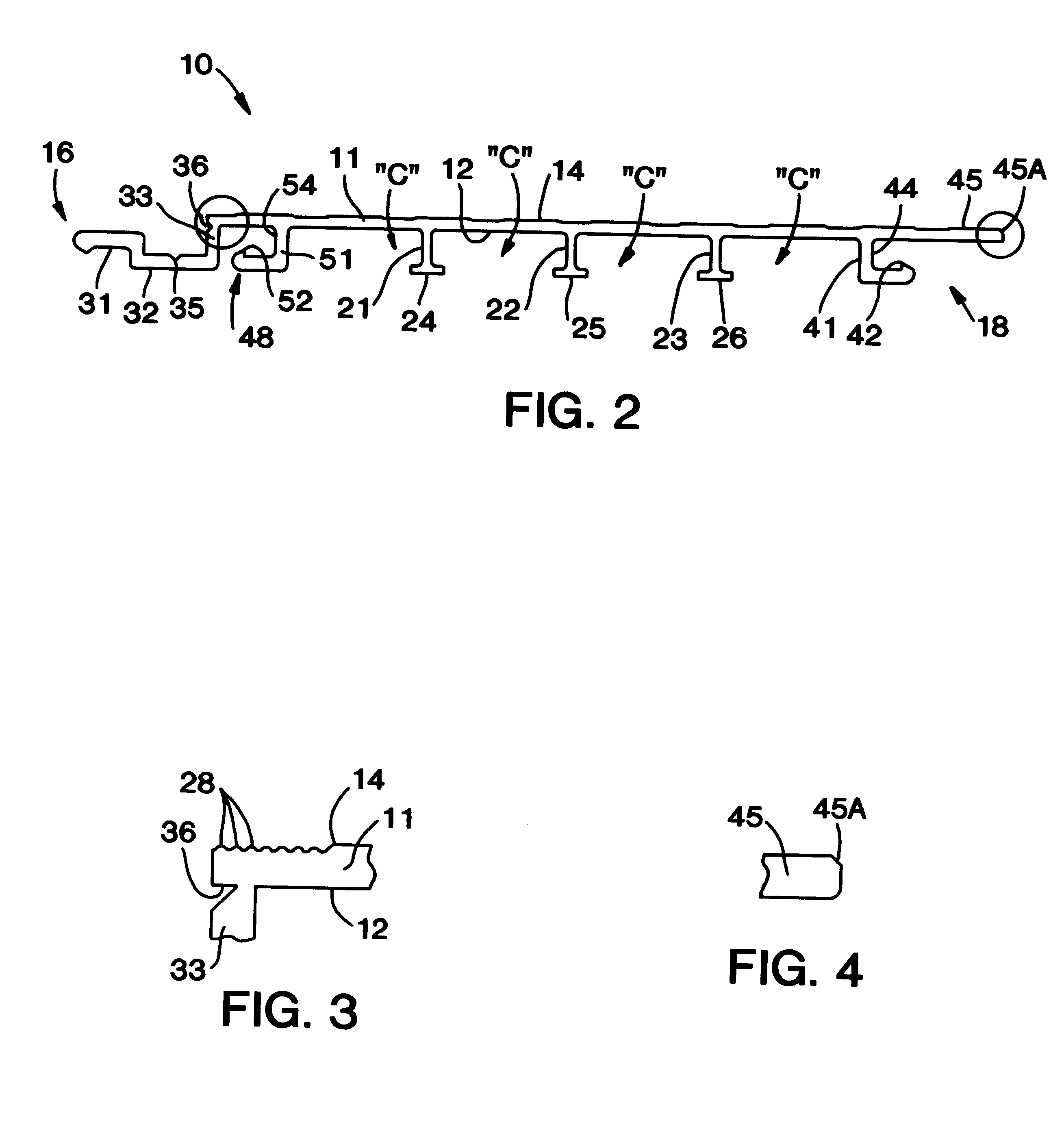
Referring now specifically to the drawings, a modular cladding element according to the present invention is illustrated in FIG. 1 and shown generally at reference numeral 10. The cladding element 10 is particularly applicable for being assembled together with a number of other elements to clad the surface of a wood deck "D" or other underlying structure. The cladding elements 10 cooperate to provide a generally maintenance free, wear-resistant surface that is attractive, easy to clean, convenient to install, and relatively inexpensive. Preferably, each cladding element 10 is integrally molded of a durable PVC plastic. A single cladding element 10 is described below with reference to FIG. 2.

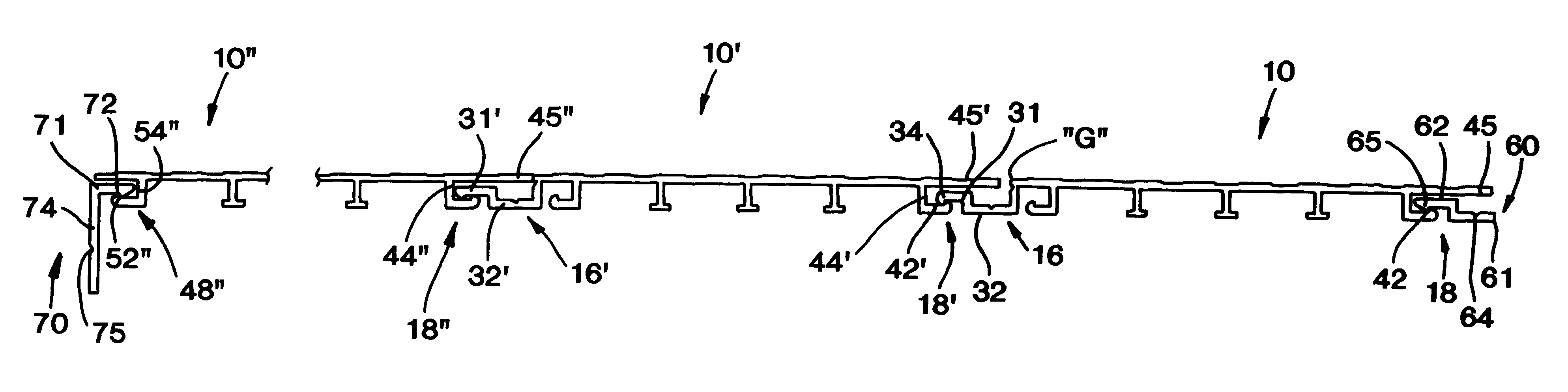
The cladding element 10 includes a panel 11 with inside and outside major surfaces 12 and 14, and complementary male and female fasteners 16 and 18 extending along respective opposing sides. A number of spaced longitudinal support ribs 21, 22, and 23 are formed with the inside major surface 12 of...


PUM

PropertyMeasurementUnit
Distanceaaaaaaaaaa

Abstract

A modular cladding element cooperates with an assembly of cladding elements to clad a surface of an underlying structure. The cladding element includes a cladding panel having opposed inside and outside major surfaces, first and second opposed sides, and first and second opposed ends. A removable male fastener is integrally formed along the first side of the panel, and is adapted for entering a complementary fastener of an adjacent cladding element when positioned on the first side of the panel. The male fastener is removable in the absence of a complementary cladding element positioned on the first side of the panel. A first female fastener is integrally formed along the opposed second side of the panel, and defines a first opening adapted for receiving a complementary fastener of an adjacent cladding element positioned on the second side of the panel. A second female fastener is integrally formed adjacent the male fastener on the first side of the panel. Upon removing the male fastener, the second female fastener defines a second opening adapted for receiving a complementary fastener of an adjacent cladding element on the first side of the panel.

Description

TECHNICAL FIELD AND BACKGROUND OF INVENTIONThe present invention relates to a modular cladding element, and an assembly of cladding elements particularly adapted for covering the surface of an underlying structure, such as a wood deck, porch, or boat pier. The invention provides a generally maintenance free, wear-resistant surface that is attractive, easy to clean, convenient to install, and relatively inexpensive.Many prior art cladding and modular deck elements are designed to mate with adjacent elements along respective sides using, for example, complementary integrally-formed fasteners. A precise fit and arrangement is generally required in order to properly assemble the elements on the structure being covered. A problem arises when it becomes necessary or desirable to position the elements such that the same type of fasteners of adjacent elements are arranged side by side. In this case, the elements generally cannot be conveniently and readily fitted together.The present invent...

Claims


Application Information

Patent Timeline
IPC IPC(8): C08L23/00C08L23/10C08L23/16E01C5/00E04C2/34E04F15/10E01C5/20E04C2/20E04F11/18E04C3/30E04C2/10E04B2/90E04F13/00E04F15/00
CPCC08L23/10C08L23/16E01C5/20E04C2/20E04C2/34E04C3/30E04F11/1842E04F15/10C08L2207/04C08L2312/00E01C2201/12E01C2201/16E04F2201/0115C08L2666/04C08L2666/02E04F15/105
Inventor DAVIS, HARRY H.
Owner L B PLASTICS
Why Eureka
Try Eureka