Capillary immunoassay and device therefor comprising mobilizable particulate labelled reagents

a technology of mobilizable particulate and immunoassay, which is applied in the field of analytical devices, can solve problems such as the introduction of the possibility of error

Inactive Publication Date: 2001-05-08
CONOPCO INC D B A UNILEVER
View PDF202 Cites 554 Cited by
  • Summary
  • Abstract
  • Description
  • Claims
  • Application Information

AI Technical Summary

Benefits of technology

A typical embodiment of the invention is an analytical test device comprising a hollow casing constructed of moisture-impervious solid material containing a dry porous carrier which communicates directly or indirectly with the exterior of the casing such that a liquid test sample can be applied to the porous carrier, the device also containing a labelled specific binding reagent for an analyte which labelled specific binding reagent is freely mobile within the porous carrier when in the moist state, and unlabelled specific binding reagent for the same analyte which unlabelled reagent is permanently immobilised in a detection zone on the carrier material and is therefore not mobile in the moist state, the relative positioning of the labelled reagent and detection zone being such that liquid sample applied to the device can pick up labelled reagent and thereafter permeate into the detection zone, and the device incorporating means enabling the extent (if any) to which the labelled reagent becomes in the detection zone to be observed.
Preferably, the immobilised reagent in the second zone is impregnated through the thickness of the carrier in the second zone (e.g. throughout the thickness of the sheet or strip if the carrier is in this form). Such impregnation can enhance the extent to which the immobilised reagent can capture any analyte present in the migrating sample.

Problems solved by technology

These operations necessarily involve time, and introduce the possibility of error.

Method used


Image

  • Capillary immunoassay and device therefor comprising mobilizable particulate labelled reagents
  • Capillary immunoassay and device therefor comprising mobilizable particulate labelled reagents
  • Capillary immunoassay and device therefor comprising mobilizable particulate labelled reagents

Examples


embodiment 2

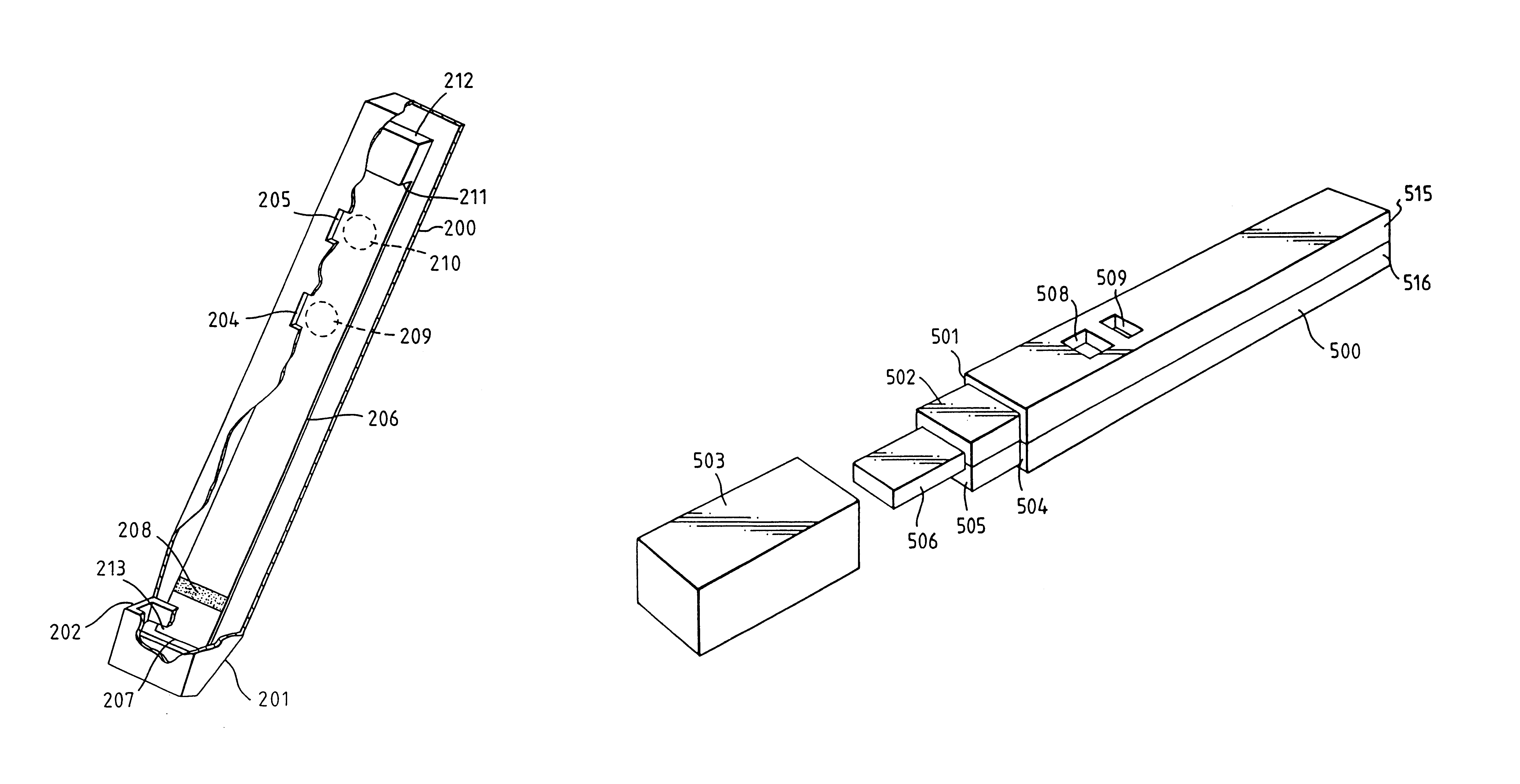
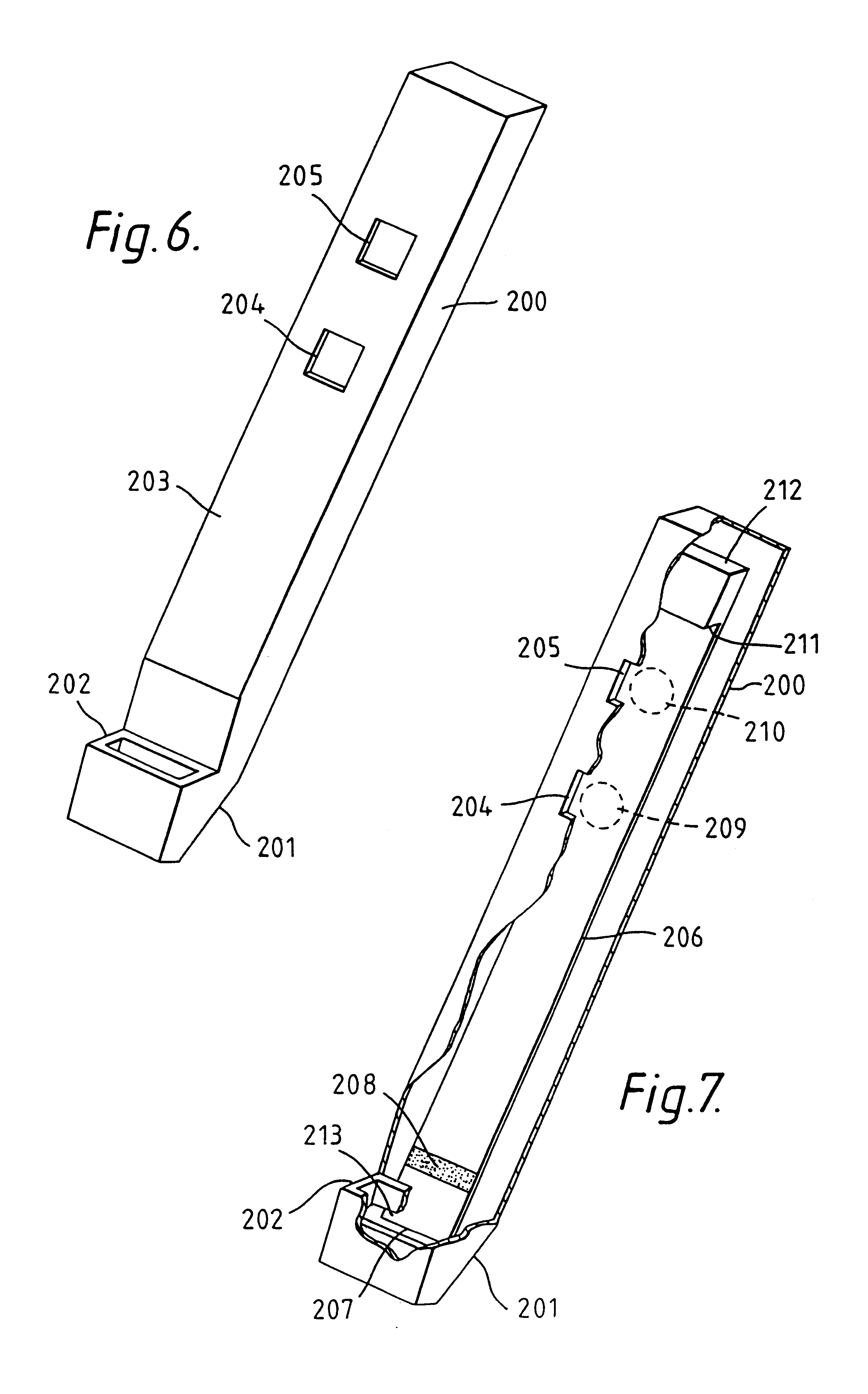
FIGS. 6 and 7 of the accompanying drawings illustrate another test device according to the invention. FIG. 6 illustrates the complete device viewed from the front, and FIG. 7 depicts the same device partially cut away to reveal details of a porous test strip contained within the body of the device.

Referring to FIG. 6, the device comprises an elongate body 200 terminating at its lower end 201 in a small integral receptacle 202 which can hold a predetermined volume of a liquid sample, eg urine. The front face 203 of the body 200 incorporates two square small square apertures or windows 204 and 205 located one above the other.

Referring to FIG. 7, the elongate portion of the body 200 is hollow and incorporates a test strip 206 running almost the full height of the body. This test strip is of similar construction to those described under Embodiment 1, and incorporates near its lower end 207 a horizontal zone 208 bearing a labelled specific binding reagent that can freely migrate in the s...

embodiment 3

FIG. 8 of the accompanying drawings represents an isometric view of an assay device in accordance with the invention, and FIG. 9 represents a cross-sectional side elevation of the device shown in FIG. 8.

Referring to FIG. 8, the device comprises a housing or casing 500 of elongate rectangular form having at one end 501 a portion 502 of reduced cross-sectional area. A cap 503 can be fitted onto portion 502 and can abut against the shoulder 504 at end 501 of the housing. Cap 503 is shown separated from housing 500. Extending beyond end 505 of portion 502 is a porous member 506. When cap 503 is fitted onto portion 502 of the housing, it covers porous member 506. Upper face 507 of housing 500 incorporates two apertures 508 and 509.

Referring to FIG. 9, it can be seen that housing 500 is of hollow construction. Porous member 506 extends into housing 500 and contacts a strip of porous carrier material 510. Porous member 506 and strip 510 overlap to ensure that there is adequate contact betw...

embodiment 4

FIGS. 11 and 12 illustrate another embodiment of the invention, which is seen in plan view in FIG. 11 and in cross-section in FIG. 12, the cross-section being an elevation on the line 12--12 seen in FIG. 11.

Referring to FIG. 11, the test device comprises a flat rectangular casing 600 incorporating a centrally disposed rectangular aperture 601, adjacent the left hand end 602, and two further apertures 603 and 604 near the mid point of the device and arranged such that apertures 601, 603 and 604 lie on the central longitudinal axis of the device corresponding to line 12--12. Although all three apertures are illustrated as being rectangular, their actual shape is not critical.

Referring to the cross-section seen in FIG. 12, the device is hollow and incorporates within it a porous sample receiving member adjacent end 602 of casing 600 and lying directly beneath aperture 601. A test strip of similar construction to that described with reference to Embodiment 4, comprising a porous strip 6...


PUM

PropertyMeasurementUnit
pore sizeaaaaaaaaaa
pore sizeaaaaaaaaaa
diameteraaaaaaaaaa

Abstract

An analytical test device useful for example in pregnancy testing, comprises a hollow casing (500) constructed of moisture-impervious solid material, such as plastics materials, containing a dry porous carrier (510) which communicates indirectly with the exterior of the casing via a bibulous sample receiving member (506) which protrudes from the casing such that a liquid test sample can be applied to the receiving member and permeate therefrom to the porous carrier, the carrier containing in a first zone a labelled specific binding reagent is freely mobile within the porous carrier when in the moist state, and in a second zone spatially distinct from the first zone unlabelled specific binding reagent for the same analyte which unlabelled reagent is permanently immobilized on the carrier material and is therefore not mobile in the moist state, the two zones being arranged such that liquid sample applied to the porous carrier can permeate via the first zone into the second zone, and the device incorporating means, such as an aperture (508) in the casing, enabling the extent (if any) to which the labelled reagent becomes bound in the second zone to be observed. Preferably the device includes a removable cap for the protruding bibulous member.

Description

1. Field of the InventionThe present invention relates to analytical devices which are suitable for use in the home, clinic or doctor's surgery and which are intended to given an analytical result which is rapid and which requires the minimum degree of skill and involvement from the user.2. Description of the Related ArtThe use of test devices in the home to test for pregnancy and fertile period (ovulation) is now commonplace, and a wide variety of test devices and kits are available commercially. Without exception, the commercially-available devices all require the user to perform a sequence of operations before the test result is observable. These operations necessarily involve time, and introduce the possibility of error.It is an object of the present invention to provide a test device which is readily usable by an unskilled person and which preferably merely requires that some portion of the device is contacted with the sample (e.g. a urine stream in the case of a pregnancy or o...

Claims


Application Information

Patent Timeline
Patent Type & Authority Patents(United States)
IPC IPC(8): G01N33/548G01N33/549G01N33/68G01N33/58G01N33/76G01N33/544G01N33/558G01N33/543G01N33/74G01N30/90G01N30/00G01N37/00G01N33/53
CPCG01N33/54366G01N33/54386G01N33/548G01N33/549G01N33/558G01N33/58G01N33/689G01N33/76G01N30/90G01N2800/368Y10S435/81Y10S435/975Y10S436/906Y10S435/962Y10S435/97Y10S436/817Y10S435/805Y10S436/81Y10S436/805Y10S436/818Y10S435/969Y10S436/814G01N33/54388
Inventor MAY, KEITHPRIOR, MICHAEL EVANSRICHARDS, IAN
Owner CONOPCO INC D B A UNILEVER
Why Eureka
Try Eureka