Differential interference contrast microscope and microscopic image processing system using the same

a contrast microscope and microscopic image technology, applied in the field of differential interference contrast microscopes, can solve the problems of reducing the resolution of the image, liable to be rather expensive, and the cost of preparing a plurality of expensive nomarski prisms becomes very high

Inactive Publication Date: 2001-05-08
OLYMPUS OPTICAL CO LTD
View PDF7 Cites 6 Cited by
  • Summary
  • Abstract
  • Description
  • Claims
  • Application Information

AI Technical Summary

Benefits of technology

It is another object of the invention to provide a novel and useful differential interference contrast microscope of reflection type, in which an amount of wavefront shear can be changed by a simple construction in a less expensive manner.
In the differential interference contrast microscope of transmission type according to the invention, the polarized light combining means is not formed by a conventional Nomarski prism, and is arranged at such a position that the two linearly polarized light rays having the mutually orthogonal vibrating directions propagate in parallel with each other and are combined with each other on the same optical axis in accordance with a variable amount of wavefront shear introduced by the polarized light separating means. By constructing the polarized light combining means in this manner, it is possible to decrease the number of Nomarski prisms upon compared with the above mentioned known differential interference contrast microscope proposed by M. Pluta.
In this differential interference contrast microscope of transmission type, since the separation of the linearly polarized light ray into the two linearly polarized light rays with mutually orthogonal vibrating directions and the combination of these two linearly polarized light rays are performed by the single polarized light separating and combining means, the construction can be simpler and a cost can be decreased.
In this manner, in the differential interference contrast microscope of reflection type according to the invention, an amount of wavefront shear between the two linearly polarized light rays on the object under inspection can be changed by using the single polarized light separating and combining means, and thus the construction becomes simple and less expensive.

Problems solved by technology

However, when an amount of wavefront shear is increased beyond the resolving power of the objective lens of the microscope, a so-called double image is inspected to decrease the resolution of the image.
For instance, not only the above mentioned microscopic image processing system using the contrast enhancing method, but also a step measuring device for inspecting a step of an object under inspection by utilizing the differential interference contrast, a phase difference measuring device for measuring a phase distribution of a transparent object under inspection by utilizing the differential interference contrast and a position detecting device for detection a position of an alignment mark on a semiconductor wafer have encountered the same problem.
It should be noted that since the Nomarski prism is manufactured by precisely processing the birefringent crystal, it is liable to be rather expensive.
Therefore, a cost for preparing a plurality of expensive Nomarski prisms becomes very high.
Moreover, even if a plurality of Nomarski prisms are prepared, each of the prisms has their own specific shear amounts of wavefront, an inspection could not be always possible with an optimum amount of wavefront shear.
However, in this known differential interference contrast microscope, there is a problem that a positional shift of image might occur upon the rotation of the Nomarski prisms when surfaces of the Nomarski prisms are not in parallel with each other.
Moreover, this microscope requires four expensive Nomarski prisms instead of two Nomarski prisms in the conventional differential interference contrast microscope, and thus a cost is apparently increased.
However, when a shear amount is decreased, a contrast of the differential interference contrast image might become lower and the alignment of the object under inspection could not be performed easily with the naked eye.
However, if the wavefront shear is larger than a structure of the object to be inspected, the ordinary and extraordinary light rays could not be made incident upon a desired portion of the object and the measurement could not be carried out.

Method used


Image

  • Differential interference contrast microscope and microscopic image processing system using the same
  • Differential interference contrast microscope and microscopic image processing system using the same
  • Differential interference contrast microscope and microscopic image processing system using the same

Examples


first embodiment

FIG. 3 is a schematic view showing the differential interference contrast microscope of transmission type according to the invention. A light ray emitted from an illuminating light source 61 is converted by a polarizer 62 constituting the first polarizing means into a linearly polarized light ray, and then the linearly polarized light ray is made incident upon a polarized light separating means 63 and is divided into two linearly polarized light rays whose vibrating directions are mutually orthogonal. According to the invention, the polarized light separating means 63 is constructed such that an amount of wavefront shear between said two linearly polarized light rays can be changed continuously. For instance, the polarized light separating means 63 may be constructed by a pair of wedge-shaped crystal plates, at least one of which is movable in a direction perpendicular to an optical axis.

In the present emodiment, the two linearly polarized light rays with orthogonal vibrating direct...

second embodiment

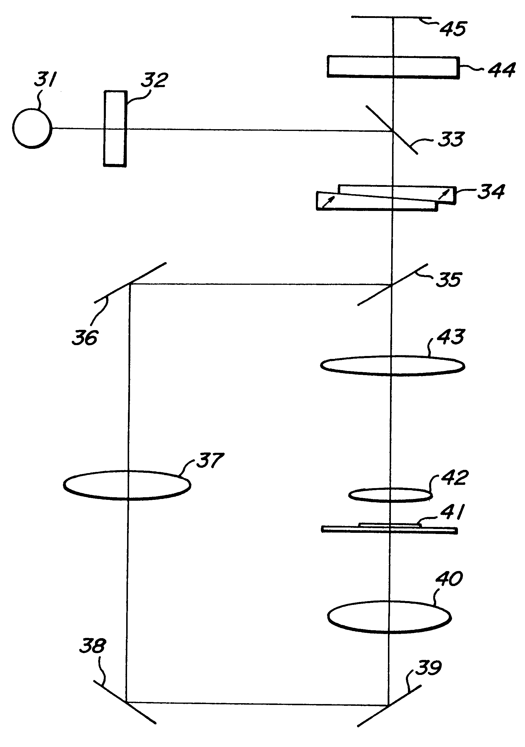
FIG. 7 is a schematic view showing the differential interference contrast microscope of transmission type according to the invention. In the present embodiment, an illumination light ray emitted by an illumination light source 31 is converted into a linearly polarized light ray by an analyzer 32 constituting the first polarizing means, and then the thus linearly polarized light ray is reflected by a half mirror 33 and is made incident upon a polarized light separating and combining means 34, in which an amount of wavefront shear can be changed. Then, two linearly polarized light rays having mutually orthogonal vibrating directions emanate from the polarized light separating and combining means 34 in parallel with each other. These linearly polarized light rays are reflected by a half mirror 35, and are made incident upon an object 41 under inspection by means of reflection mirror 36, illuminating lens 37, reflection mirrors 38 and 39 and illuminating lens 40. The two linearly polari...

third embodiment

FIG. 9 is a schematic view illustrating the differential interference contrast microscope of transmission type according to the invention, in which the separation and combination of the two linearly polarized light rays are carried out by one and same polarized light separating and combining means. In this embodiment, a light ray emitted by an illumination light source 81 is converted into a linearly polarized light ray by an analyzer 82, and then the linearly polarized light ray is made incident upon a first portion of a polarized light separating and combining means 84 by means of a mirror 83a and is separated into two linearly polarized light rays which have mutually orthogonal vibrating directions and propagate in parallel with each other. The polarized light separating and combining means 84 may be formed by two wedge-shaped crystal plates like as the polarized light separating and combining means 34 shown in FIG. 8. Then, an amount of wavefront shear can be adjusted by moving ...


PUM


Abstract

A differential interference contrast microscope including an illuminating light source, a polarizer for converting an illumination light ray into a linearly polarized light, a polarized light separating means for dividing the linearly polarized light ray into two linearly polarized light rays having mutually orthogonal vibrating directions, an illuminating optical system for projecting the two linearly polarized light rays onto an object under inspection, a polarized light combining unit for combining the two linearly polarized light rays on a same optical path via an inspecting optical system, an analyzer for forming a differential interference contrast image on an imaging plane. The polarized light separating unit is constructed such that an amount of wavefront shear between the two linearly polarized light rays on the object can be changed, and the polarized light combining unit is arranged between the object and the analyzer at such a position that the two linearly polarized light rays propagate in parallel with each other and is constructed such that the two linearly polarized light rays can be combined with each other in accordance with the shear amount of wavefront introduced by the polarized light separating unit.

Description

1. Field of the InventionThe present invention relates to a differential interference contrast microscope for use in investigating transparent biological substances or specimens such as cells and bacteria as well as a fine pattern of projections and depressions formed on a surface of a semiconductor substrate, e.g. a silicon wafer. The present invention also relates to a microscopic image processing system using such a differential interference contrast microscope.2. Related Art StatementFIG. 1 shows a known differential interference contrast microscope of transmission type. The microscope comprises, in addition to illumination light source 1, condenser lens 2 and objective lens 3 which are generally provided in a conventional optical microscope, polarizer 5 and Nomarski prism 6 which are arranged in this order between the illumination light source 1 and the condenser lens 2, and Nomarski prism 7 and analyzer 8 which are arranged in this order between the objective lens 3 and an ima...

Claims


Application Information

Patent Timeline
Patent Type & Authority Patents(United States)
IPC IPC(8): G01B9/04G02B21/06G02B26/00G02B21/14G02B27/28G02B21/00
CPCG01B9/04G02B21/14G02B26/00G02B27/283
Inventor KUSAKA, KENICHI
Owner OLYMPUS OPTICAL CO LTD
Why Eureka
Try Eureka