
Multimedia computer system

a computer system and multimedia technology, applied in the computer field, can solve the problems of increasing the cost of the entire system, the video decoder in the media player cannot be used to decode an mpeg title recorded in a medium other than that in the media player, and the image quality is undesirably degraded, so as to achieve the effect of simplifying the hardware configuration

Inactive Publication Date: 2001-05-08
KK TOSHIBA
View PDF20 Cites 22 Cited by
  • Summary
  • Abstract
  • Description
  • Claims
  • Application Information

AI Technical Summary

Benefits of technology

Enables high-quality, cost-effective reproduction of large-capacity multimedia information including main pictures, sub-pictures, and sound data on a personal computer without the need for two video decoders or a dedicated expansion board, using a simplified hardware configuration.

Problems solved by technology

For this reason, in processing full-motion video data including a large quantity of image information, e.g., a movie, the image quality is undesirably degraded.
This is because the video decoder in the media player is dedicated to the player, so the video decoder in the media player cannot be used to decode an MPEG title recorded in a medium other than that in the media player, e.g., a hard disk or a CD-ROM.
For this reason, when a system in which a media player is mounted in a personal computer is constructed, two video decoders for reproducing full-motion video data are provided in the system, resulting in an increase in cost of the entire system.

Method used


Image

  • Multimedia computer system
  • Multimedia computer system
  • Multimedia computer system

Examples


second embodiment

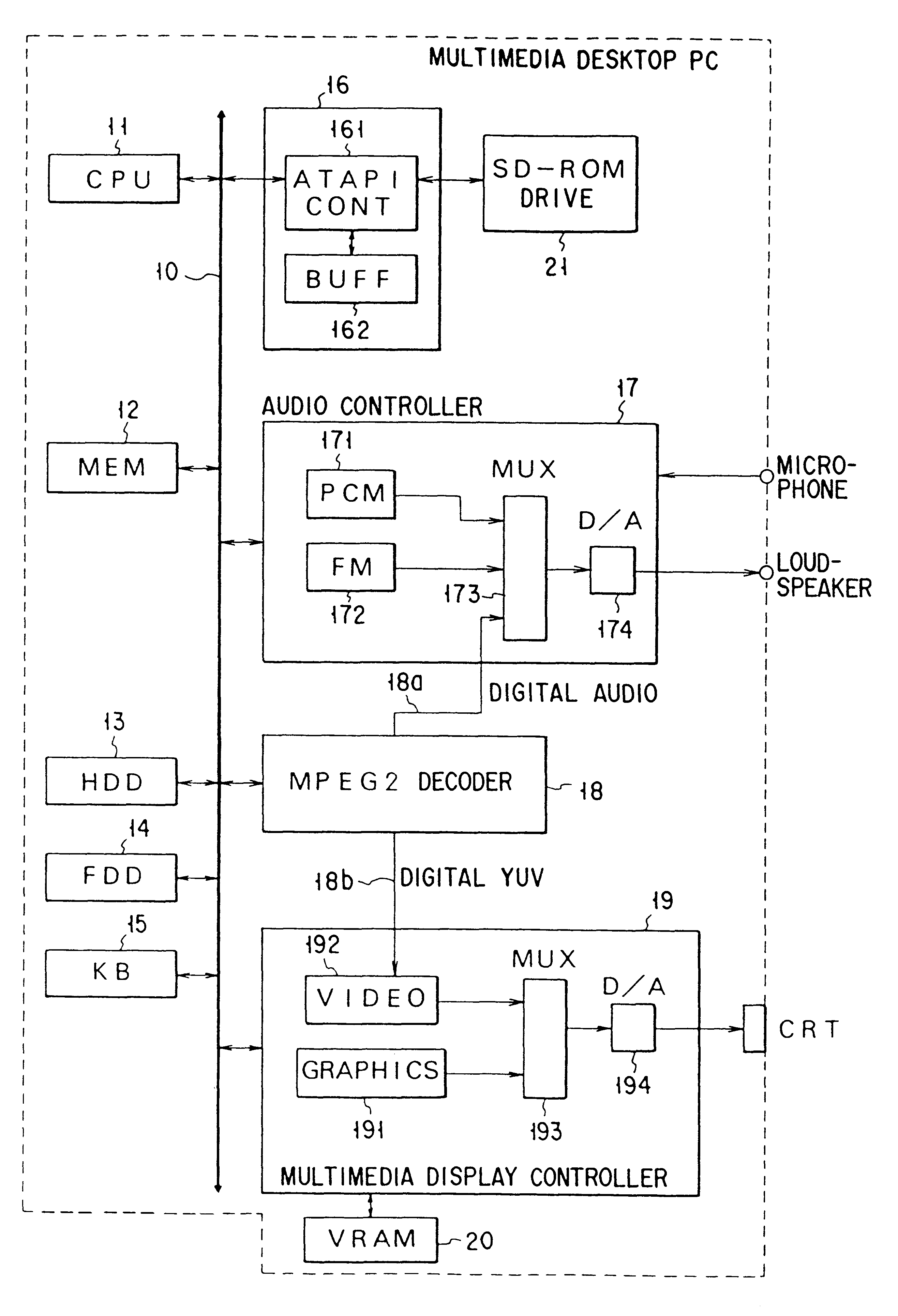
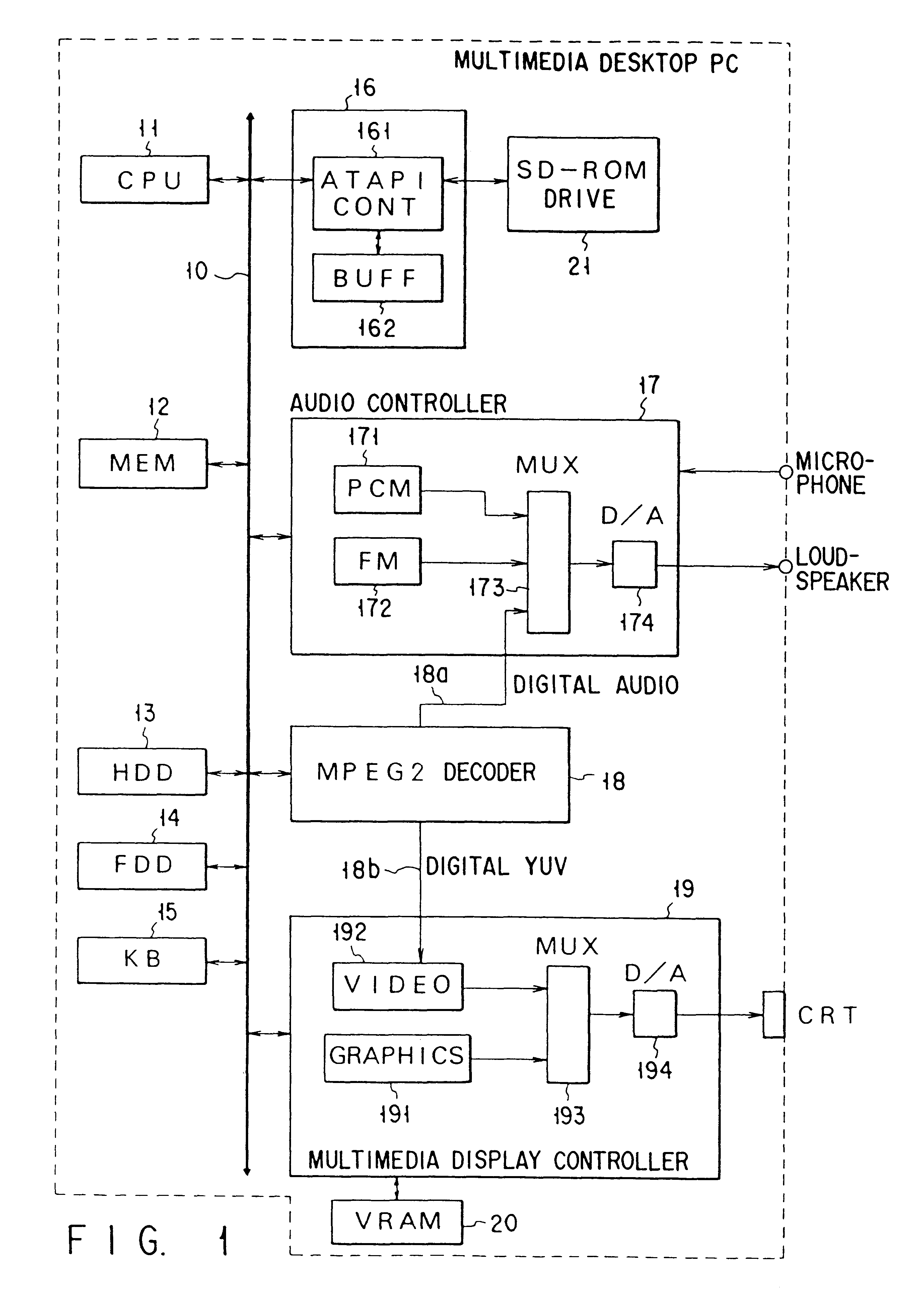
A system configuration according to the present invention will be described below with reference to FIG. 12. In the system of FIG. 12, the system configuration of the desktop personal computer system in FIG. 1 is applied to a notebook portable computer. The system in FIG. 12 differs from that in FIG. 1 only in the following point.

In this case, unlike FIG. 1, a MPEG2 video decoder 18 is realized not on a system board but on a PC card 22. At the same time, a PC card controller 23 has interfaces to an audio controller 17 and a multimedia display controller 19.

The PC card 22 complies with the PCMCIA specifications, which is mounted in the card slot of the notebook portable computer main body and connected to the PC card interface (connector) in the slot.

The PC card 22 has a CIS (Card Information Structure) 221 and an MPEG2 decoder 222. The MPEG2 decoder 222 has the same function as that of the MPEG2 video decoder 18 in FIG. 1 except the interfaces to the audio controller 17 and the mult...

third embodiment

the present invention will be described below. In this embodiment, a sub-picture is decoded by software processing by a CPU.

Reproduction of a movie recorded in a DVD-ROM drive 21 is performed by causing a CPU 11 to execute an MPEG driver 121. The MPEG driver 121 includes a sub-picture decoding function.

The sub-picture decoding function of the MPEG driver 121 provides the following three functions.

(1) Disassembling of MPEG Bit Stream

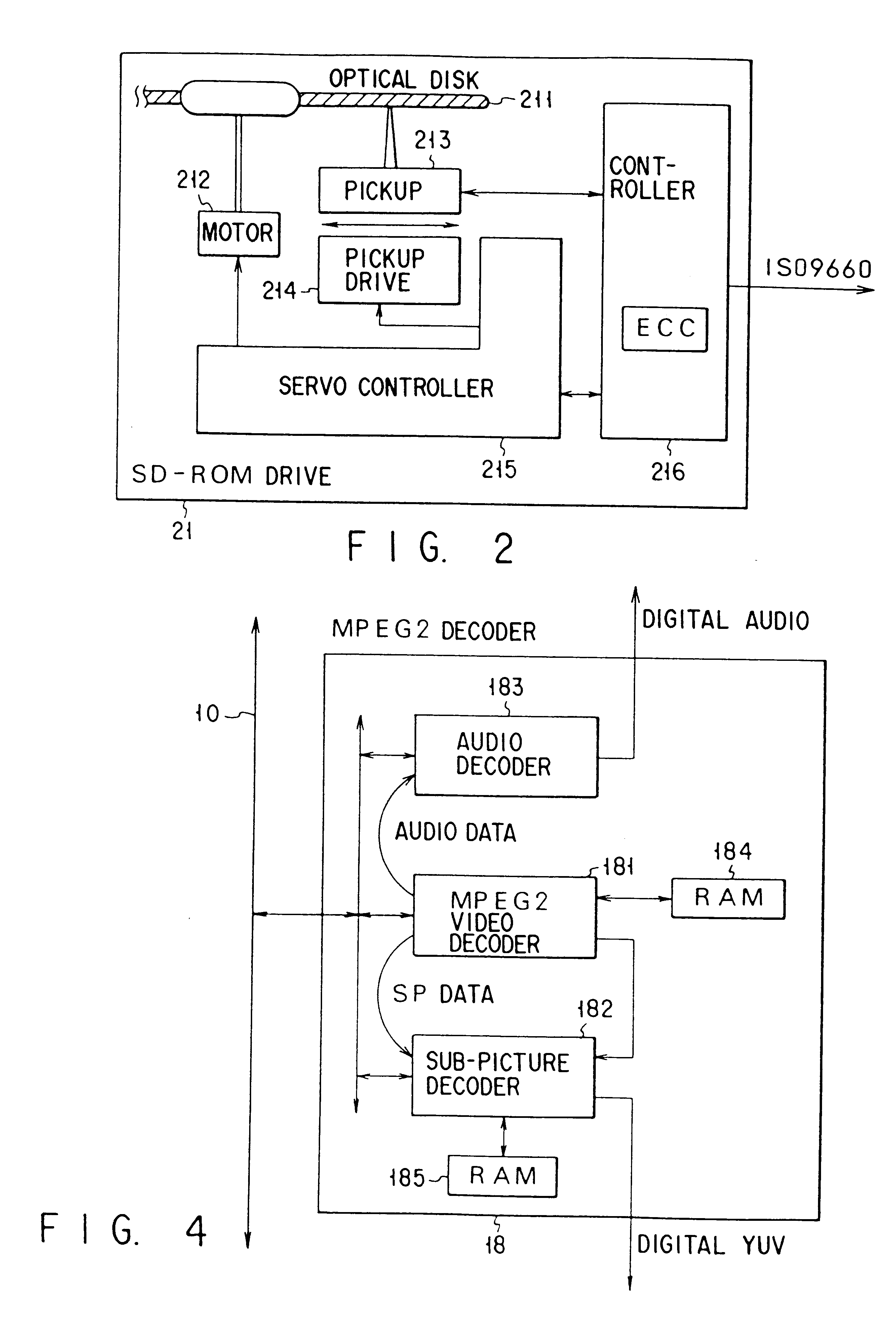
The MPEG bit stream disassembling function separates an MPEG bit stream into video packs, sub-picture packs, and audio packs and transfers the video packs and the audio packs to an MPEG2 decoder 18. This separation processing is executed in units of packs on the basis of the stream ID in FIG. 3.

(2) Decoding of Sub-picture

The sub-picture decoding function decodes the separated sub-picture packs on a system memory 12.

(3) Transfer of Sub-picture to VGA

The function of transferring sub-picture data to a VGA transfers the decoded sub-picture data to a multimedi...


PUM


Abstract

Full-motion video data with a sub-picture and sound is recorded in a DVD-ROM drive. The DVD-ROM drive is connected to an ATAPI interface. Using a data buffer of the ATAPI interface, an MPEG stream is transferred to an MPEG2 decoder on the system board at a variable rate, and video data, audio data, and a sub-picture included in the MPEG stream are decoded by the MPEG2 decoder incorporated in the system. The decoded sub-picture is drawn in a VRAM as in normal VGA graphics. The sub-picture image drawn in the VRAM is synthesized with the video from the MPEG2 decoder by a multimedia display controller and displayed on a screen.

Description

The present invention relates to a computer system and, more particularly, to a multimedia computer system which uses a disk drive unit for driving a high-density recording medium in which full-motion video data including a main picture and a sub-picture and sound data are digitally compressed and recorded to perform full-motion video display or sound reproduction.As computer technology progressed in recent years, so-called multimedia personal computers of various types have been developed. A personal computer of this type can reproduce not only text data and graphics data but also full-motion video data and sound data.Normally, full-motion video data is compressed and coded using MPEG1 (Moving Picture Image Coding Experts Group Phase 1; image format (at 30 frames per second): 350 pixels.times.240 pixels or less; coded data rate: 1.5 Mbits per second or less; coded image: frame image; motion vector prediction method: interframe prediction) and stored in a CD-ROM or the like. To deco...

Claims


Application Information

Patent Timeline
Patent Type & Authority Patents(United States)
IPC IPC(8): G06F17/30G09G5/00H04N7/26H04N7/52H04N7/50H04N5/45H04N21/2368H04N21/434
CPCG06F17/30017G09G5/00H04N5/45H04N21/2368H04N21/4341H04N19/70H04N19/46H04N19/61H04N19/44H04N19/42H04N19/423H04N19/433G09G2340/125H04N19/30H04N21/4143H04N21/4183H04N21/42646H04N21/4316H04N21/4348H04N21/8146G06F16/40
Inventor ZENDA, HIROKI
Owner KK TOSHIBA
Learn More