
Arc fault circuit breaker

a fault circuit and circuit breaker technology, applied in the field of circuit breakers, can solve the problems of bending the bimetal enough to throw it out of calibration, requiring a relatively large amount of space in an already cramped mechanical compartment, and requiring a large amount of spa

Inactive Publication Date: 2001-05-15
ABB (SCHWEIZ) AG
View PDF82 Cites 90 Cited by
  • Summary
  • Abstract
  • Description
  • Claims
  • Application Information

AI Technical Summary

Problems solved by technology

This, however, requires a relatively large amount of space within an already cramped mechanical compartment to accommodate the free movement of the bimetal.
This problem is exacerbated by having too many connections attached to the bimetal which must also be allowed to move freely as the bimetal flexes.
Additionally, making too many connections to the bimetal during assembly may bend the bimetal enough to throw it out of calibration.
However, voltage drops indicating an arc fault are small and rapid, and can be imitated by electromagnetic interference (EMI) in the sensing lines.
If the sensing lines are not properly protected, EMI may cause the sensing circuitry to trip the circuit breaker without the occurrence of arcing (false trip).
However, the twisting process is labor intensive and problematically adds to the cost of assembly.
However, shielded wires are expensive and still require connecting two wires across the bimetal in the cramped mechanical compartment, which can result in disturbing the sensitive calibration of the bimetal.

Method used


Image

  • Arc fault circuit breaker
  • Arc fault circuit breaker
  • Arc fault circuit breaker

Examples


Embodiment Construction

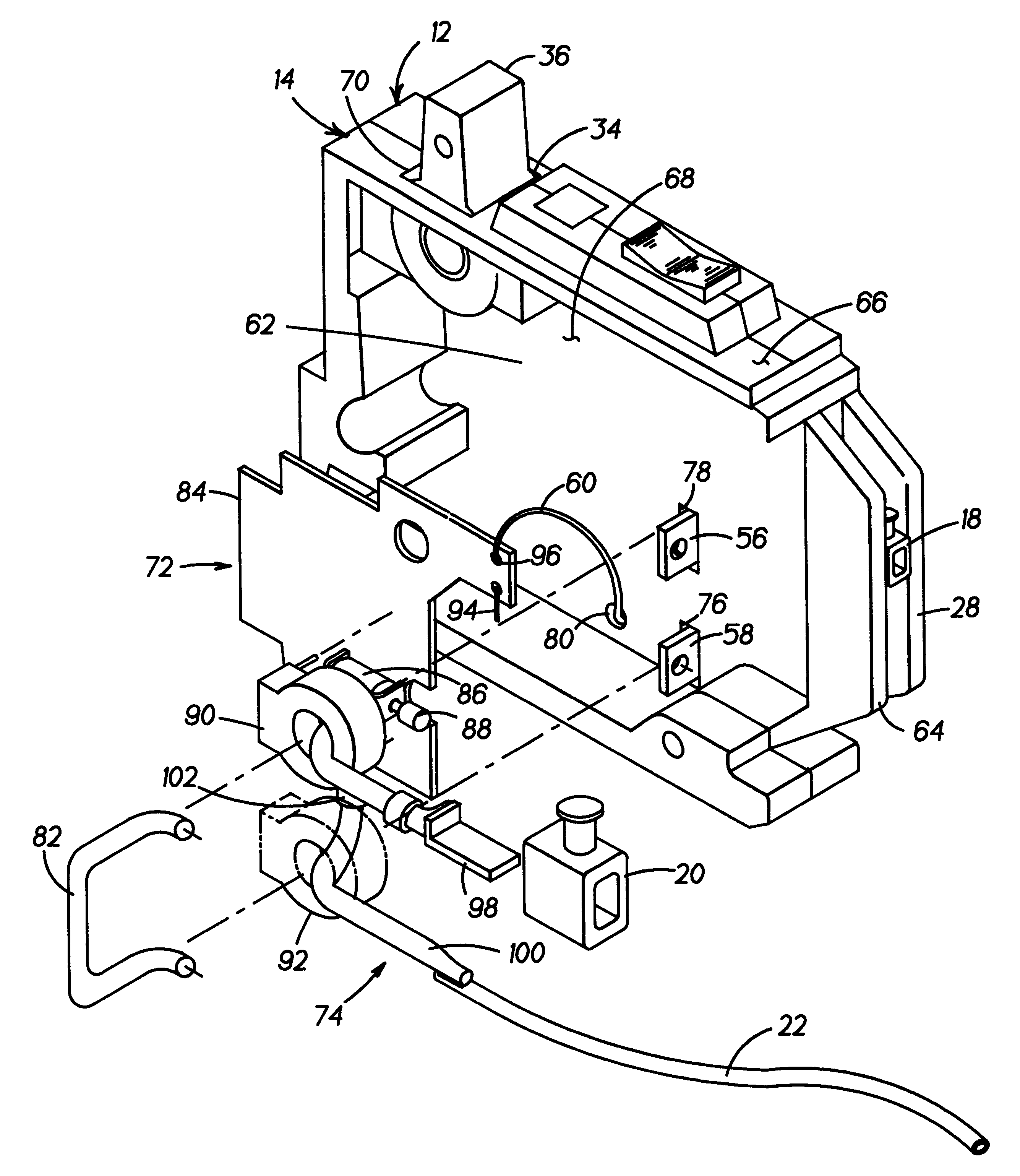
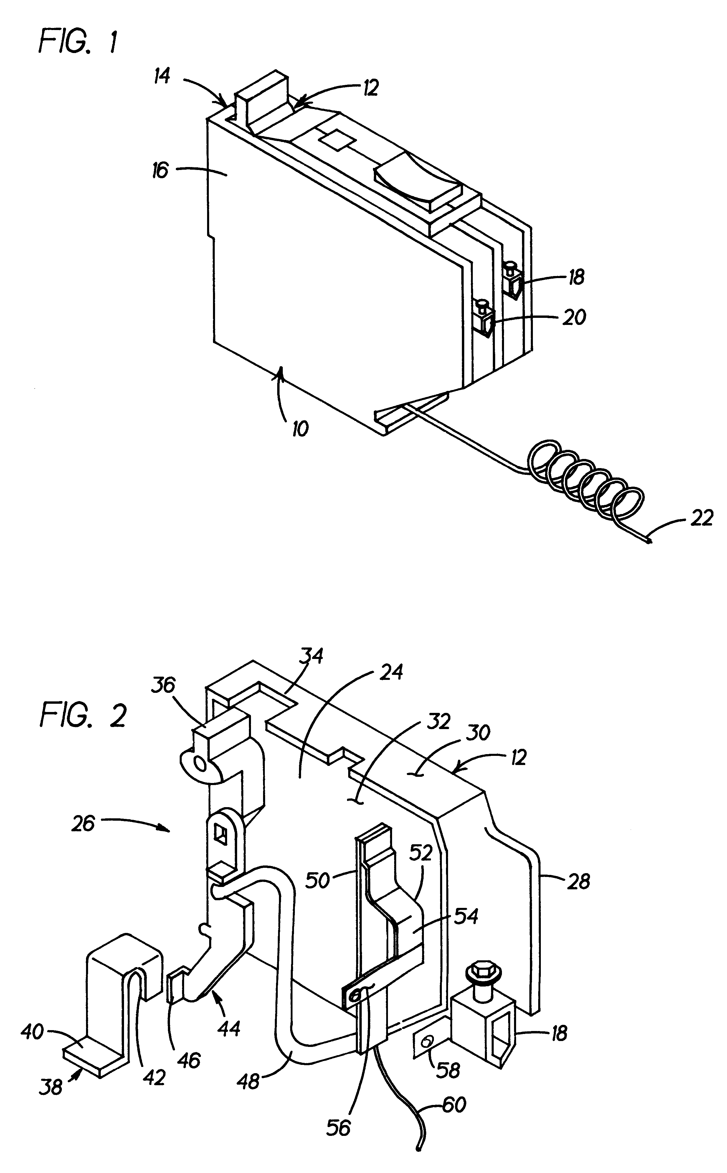
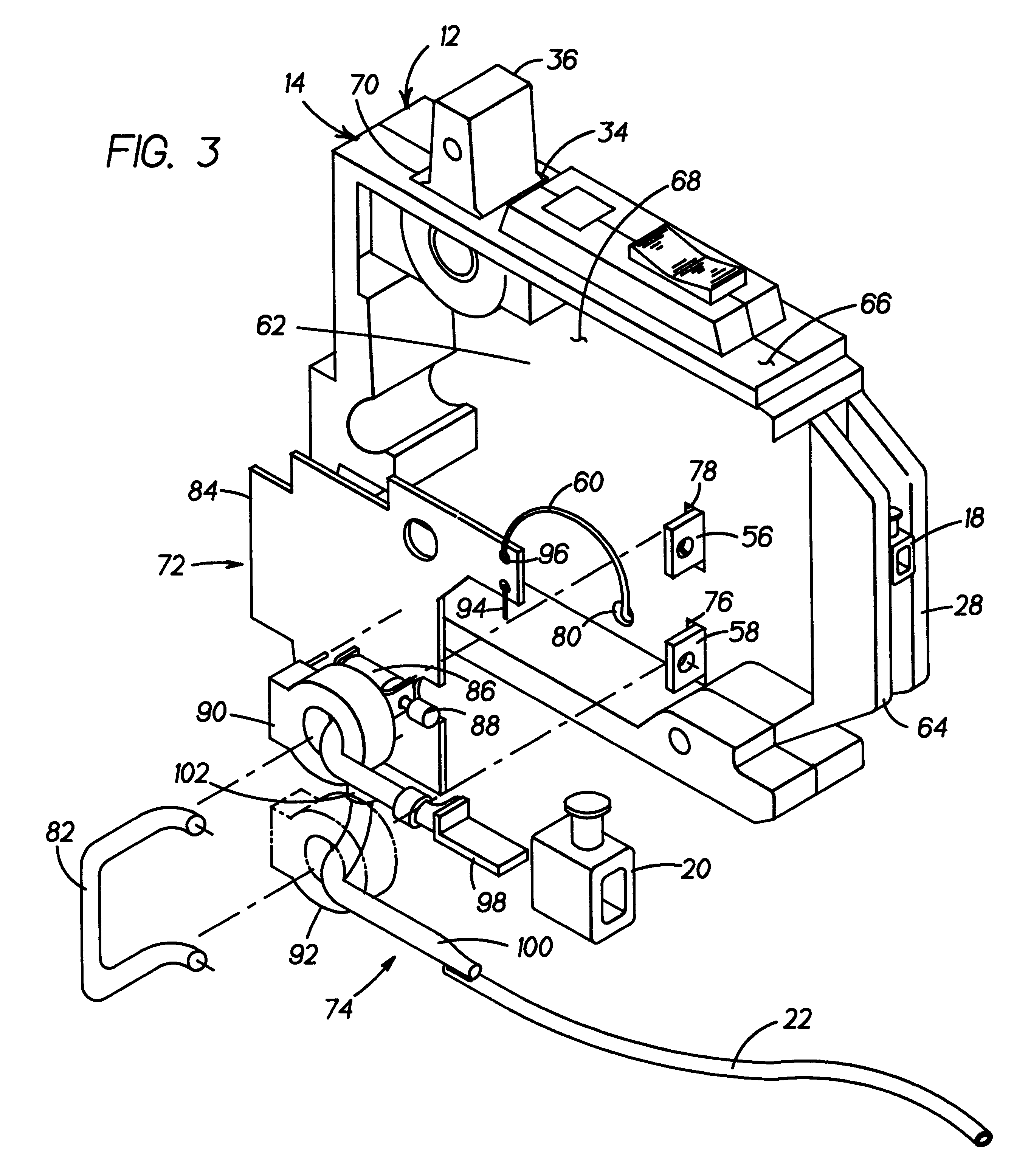
Referring to FIGS. 1, 2, and 3, an exemplary embodiment of a fully assembled, single pole, arc fault circuit breaker is shown generally at 10. Circuit breaker 10 comprises a first housing 12, a second housing 14, and a cover 16 that are assembled securely together with a plurality of permanent fasteners (not shown). First housing 12 defines a mechanical compartment 24, having load current carrying and switching components 26 disposed therein (see FIG. 2). Second housing 14 defines an electronics compartment 62, having current sensing components 72 and neutral current carrying components 74 disposed therein (see FIG. 3). A load current from a source (not shown) connects to line connection 38 (see FIG. 2), and conducts along the current carrying and switching components 26 to load lug 18 for customer connection to a load (not shown). A neutral current from the load connects to neutral lug 20 (see FIG. 3), and conducts along the neutral current carrying components 74 to neutral return ...


PUM


Abstract

An arc fault circuit breaker (10) conducting an electric current to a protected load is presented. The circuit breaker (10) has a first (mechanical) compartment (24) and a second (electrical) compartment (62). A bimetal resistor (50) is disposed within the first compartment (24) and conducts the current therethrough. The bimetal resistor (50) has a stud (56) extending into the second compartment (62). A single sense line (60) is electrically connected to the bimetal resistor (50) and routed into the second compartment (62). The sense line (60) and said stud (56) conduct a voltage signal indicative of arcing of the current. A circuit board (84) is disposed within the second compartment (62) and is connected to the sense line (60) and stud (56) within the second compartment (62) to process the voltage signal. The circuit board (84) has a first conductive path (104) electrically connected to the stud (56), and a second conductive path (106) electrically connected to the sense line (60). The first and second conductive paths (104,106) run substantially parallel and proximate to each other such that electromagnetic interference of the voltage signal is substantially reduced.

Description

BACKGROUND OF THE INVENTIONThe present invention relates generally to a circuit breaker. More specifically the present invention relates to an arc fault circuit breaker, wherein voltage is sensed across a bimetallic element and processed by current sensing components to detect the existence of an arc fault.Arc fault circuit breakers typically comprise a pair of separable contacts that open (trip) upon sensing an arcing current from line to ground, and / or from line to neutral. Arc fault circuit breakers typically use a differential transformer to measure arcing from line to ground. Detecting arcing from line to neutral is accomplished by detecting rapid changes in load current by measuring voltage drop across a relatively constant resistance, usually a bimetallic element (bimetal). Additionally, during over current conditions (i.e., above rated current) the bimetal heats up and flexes a predetermined distance to engage a primary tripping mechanism and trip the circuit breaker.Compone...

Claims


Application Information

Patent Timeline
IPC IPC(8): H01H83/00H01H71/16H01H83/14H01H71/12
CPCH01H71/123H01H71/16H01H83/144H01H2083/201H01H71/12
Inventor MASON, JR., HENRY H.SEYMOUR, RAYMOND K.GLABAU, FREDERIC W.TILGHMAN, DOUGLAS B.DESORMEAUX, JR., JOSEPH L.GUERRETTE, MICHAEL C.
Owner ABB (SCHWEIZ) AG
Learn More