Transmission

a transmission and transmission technology, applied in the field of transmission, can solve problems such as adverse effects, and achieve the effect of improving transmission

Inactive Publication Date: 2001-05-22
LUK GETRIEBE SYST
View PDF13 Cites 33 Cited by
  • Summary
  • Abstract
  • Description
  • Claims
  • Application Information

AI Technical Summary

Benefits of technology

The object underlying the present invention is to improve transmissions of the aforedescribed character as concerns their construction, cost and the mode of operation. The transmission is to be provided with an energy storing device which is rotatably confined in actual use of the transmission and does not accidentally block any of the elements.
In accordance with the invention, this is accomplished in that the energy storing device has a cross section slightly departing from a cylindrical shape, the cross section decreasing in a first axial region and increasing again in a second axial region. This ensures that, when the energy storing device is subjected to a pronounced axial stress, it assumes a shape such that the radially inner portions of the convolutions lie against an extension of the axially movable conical flange and do not migrate radially outwardly which could result in a clamping or blocking of discrete component parts of the transmission.
It is of advantage if the receptacle constitutes a circumferentially extending groove which is provided in the axially movable conical flange, which is surrounded radially by an extension and which receives at least one convolution at the end zone of the energy storing device, the convolution being supported by the extension as seen in the radial direction and being supported by the conical flange in the axial direction.
It is of advantage if the receptacle of the axially fixed element supports at least one convolution of the energy storing device, at the end region of the energy storing device, against movement outwardly as seen in the radial direction and also in the axial direction.
It is of advantage if the elastic sealing ring is disposed radially within the essentially shape-retaining annular element.

Problems solved by technology

This entails the development of a pronouced adverse effect upon the operation of the transmission.

Method used


Image

  • Transmission
  • Transmission
  • Transmission

Examples


Embodiment Construction

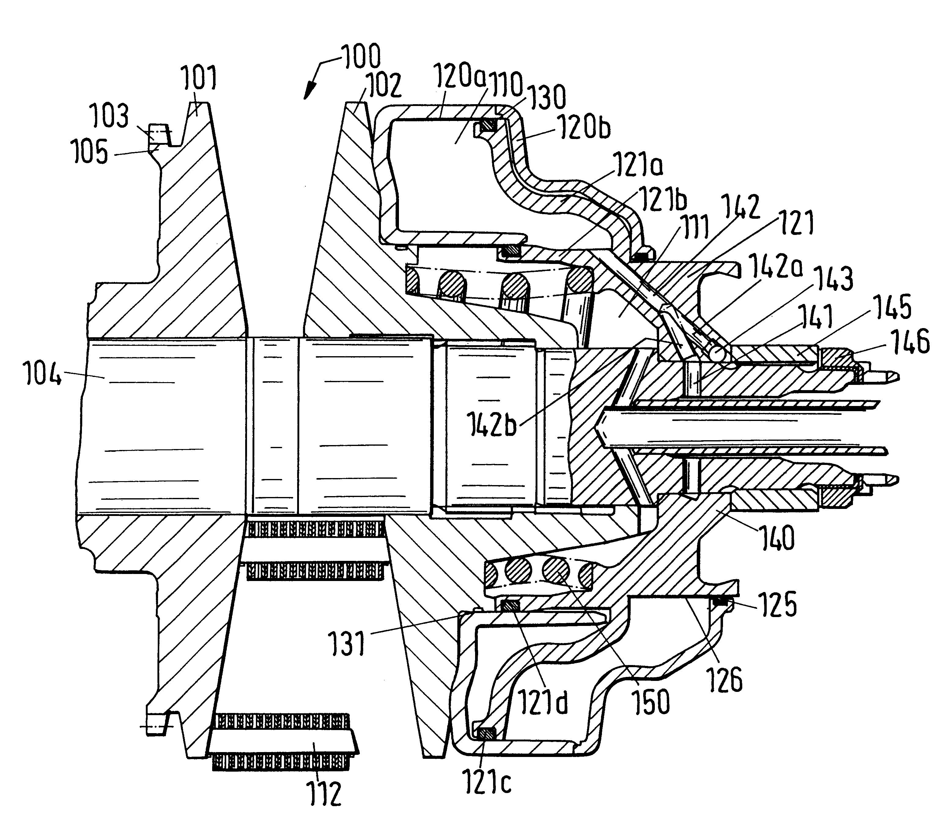
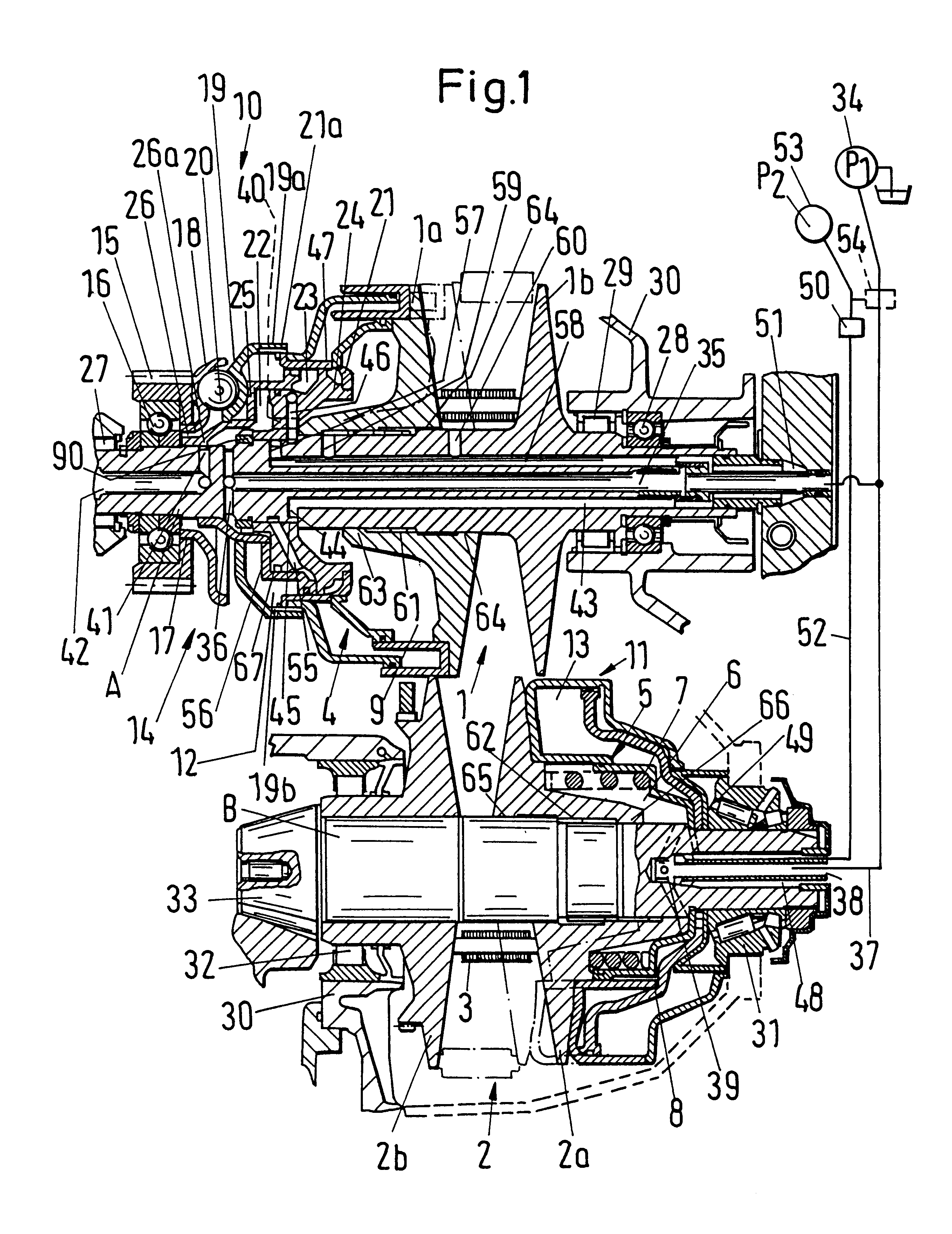
The embodiment of an infinitely variable transmission with pulleys having conical flanges, a portion of which is shown in FIG. 1, comprises a pair 1 of driving flanges which are non-rotatably mounted on a drive shaft A, and a pair 2 of flanges non-rotatably mounted on a driven shaft B. Each pair of flanges has an axially movable flange 1a and 2a, and an axially fixed flange 1b and 2b. A surrounding means in the form of a chain 3 is provided and transmits torque between the two pairs of flanges.

The upper half of the illustration of the corresponding pair 1, 2 of flanges shows those axial positions of the respective flanges 1a, 1b and 2a, 2b which correspond to the maximum transmission ratio of the transmission to a lower speed (underdrive), whereas the lower halves of these illustrations show those positions of the cooperating flanges 1a, 1b and 2a, 2b which correspond to the maximum transmission ratio to the higher speed (overdrive).

The flanges of the pair 1 are axially stressed by ...


PUM


Abstract

A continuously variable speed transmission with a first adjustable pulley on an input shaft, a second adjustable pulley on an output shaft, and an endless chain or belt trained over the pulleys employs at least one coil spring which biases one flange of one of the pulleys axially of the respective shaft. The coil spring has larger-diameter end convolutions and smaller-diameter intermediate convolutions. A plenum chamber of a torque sensor or of at least one of several piston-cylinder units-which serve to adjust the axially movable flanges of the pulleys-is bounded in part by a check valve in the form of a composite seal having a rigid annular element and an elastic annular element. One of the annular elements surrounds the other element.

Description

The invention relates to a transmission, such as an infinitely or continuously variable speed transmission with pulleys having conical flanges, with a first pair of conical flanges and a second pair of conical flanges, each pair having an axially movable and an axially fixed conical flange, and looped torque transmitting means trained over the pairs of conical flanges, with at least one energy storing device disposed to operate between an axially fixed element and an axially movable conical flange.Such transmissions became known, for example, from the published German patent application Ser. No. 195 44 644 and the corresponding U.S. Pat. No. 5,711,730. For example, such transmission can employ a coil spring, e.g., a compression spring, in order to achieve the establishment of a stress between an axially fixed element and an axially shiftable conical flange.If such transmissions employ a cylindrical spring, it can happen that, when the spring is subjected to a pronounced axial stress...

Claims


Application Information

Patent Timeline
Patent Type & Authority Patents(United States)
IPC IPC(8): F16H9/18F16H63/02F16H63/06F16H9/02
CPCF16H63/065
Inventor WALTER, BERNHARD
Owner LUK GETRIEBE SYST
Why Eureka
Try Eureka