Supply circuit for a fluorescent tube installation

US6236169B1Inactive Publication Date: 2001-05-22AMTECA

Image

  • Supply circuit for a fluorescent tube installation
  • Supply circuit for a fluorescent tube installation
  • Supply circuit for a fluorescent tube installation

Examples


Embodiment Construction

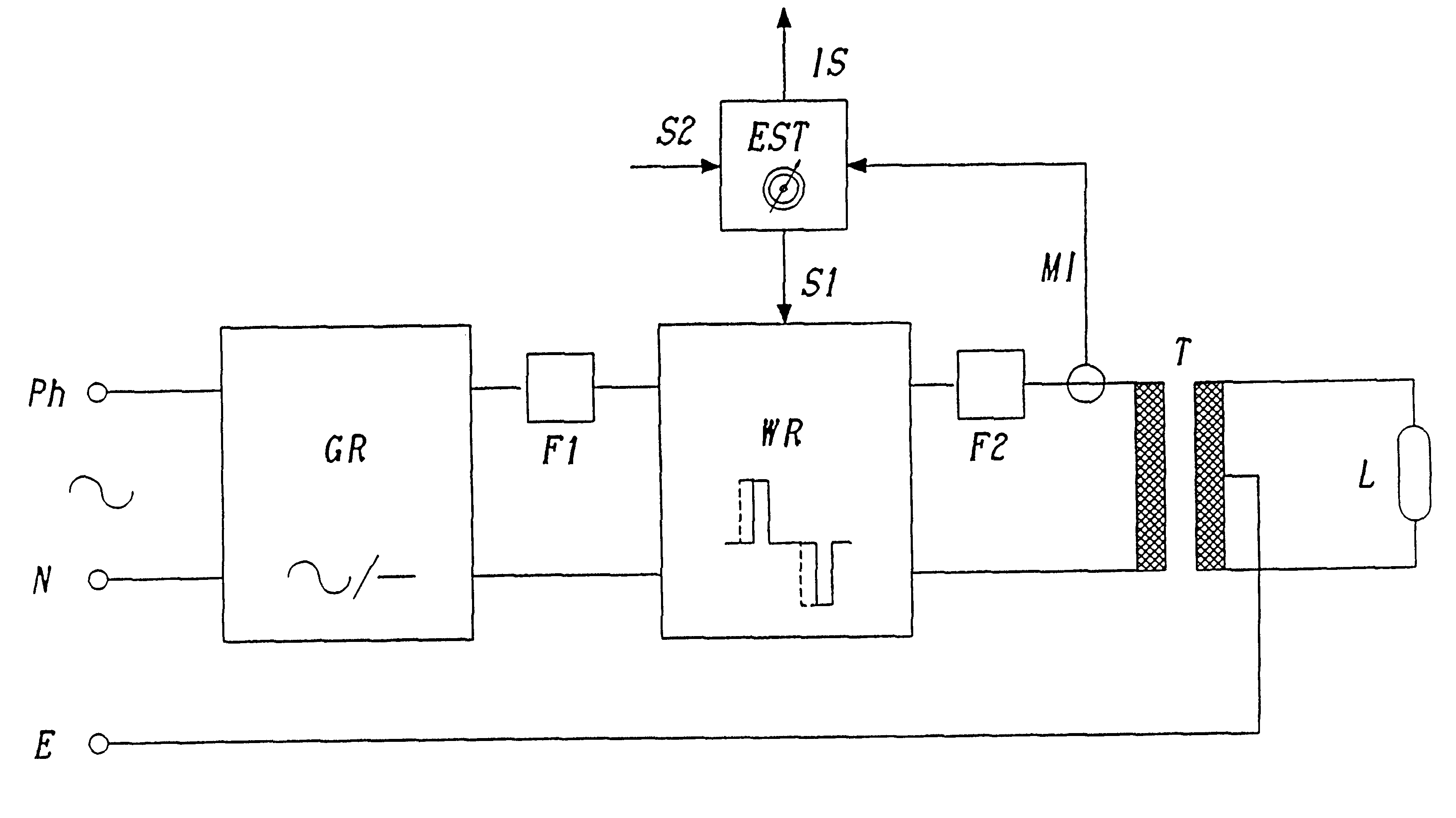
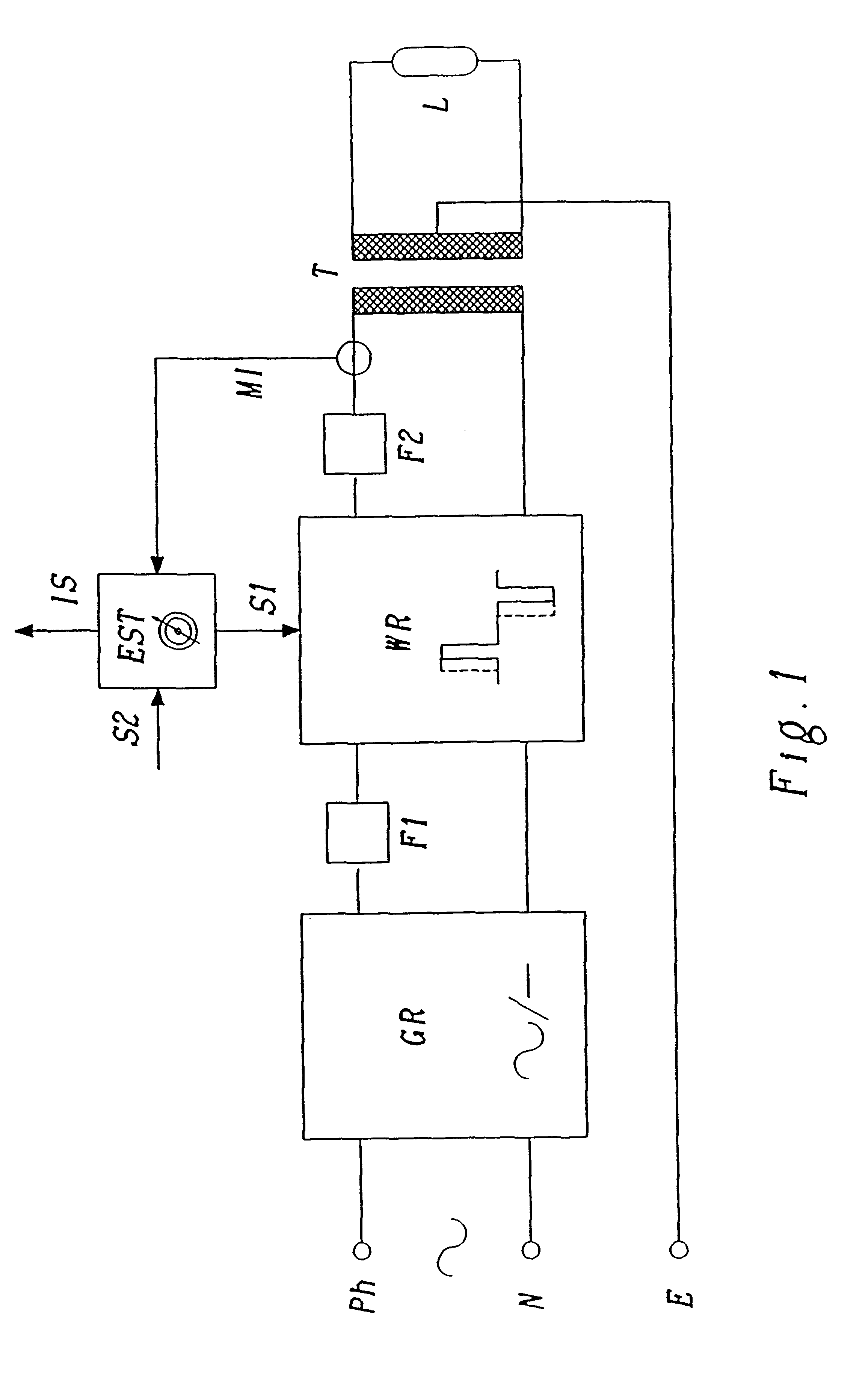
The invention has the object of describing a supply circuit for a fluorescent tube with a high voltage transformer in the lower frequency range which can be made more simply, more economically and smaller than mains frequency installations commonly used at present, and where the mentioned wide variety of different types of transformers is reduced.

This object is achieved according to the invention by a supply circuit having the characteristics given in patent claim 1.

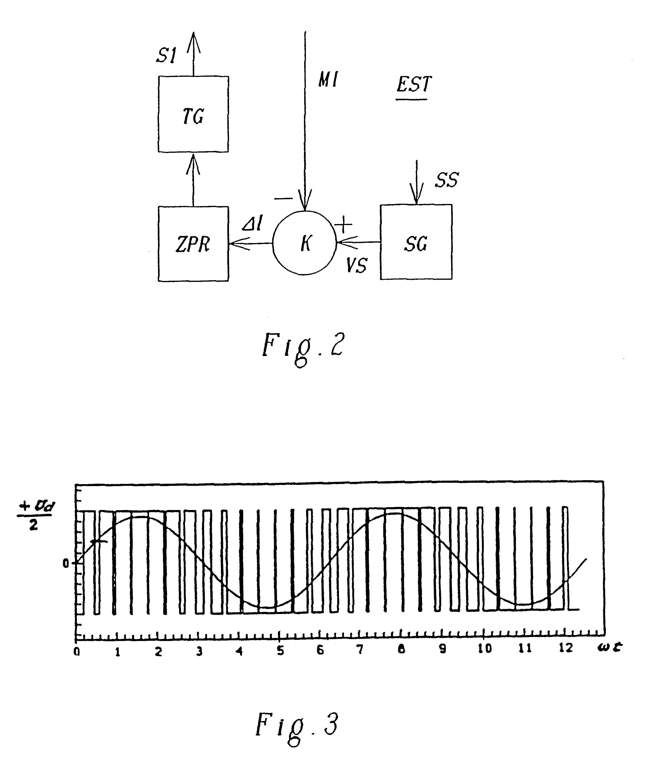
The circuit according to the invention is characterised in that, the transformer is connected on the primary side to an input voltage with a frequency of several hundred Hz, but is constructed without an air gap. An electronic control which emulates the current limiting function of an air gap is provided in the input circuit of the transformer to replace the air gap in the transformer.

As the input voltage has a frequency that is several hundred Hz greater than mains frequency, and which according to claim 2 is particular...


PUM


Abstract

A supply circuit for a fluorescent tube installation with a high-voltage transformer (T) which is connected, input-end, to a supply voltage with a frequency of several hundred Hz, and which is formed without an air gap. To replace the air gap in the transformer, an electronic regulator (EST) is nonetheless used in the supply circuit, which emulates the current-limiting function of an air gap. The frequency of the supply voltage is between 300 and 800 Hz, preferably 400 Hz. As these frequencies are higher than the usual network frequency of 50 / 60 Hz, the size and weight of the transformer can be considerably reduced.

Description

The present invention relates to a supply circuit for a fluorescent tube installation with a high voltage transformer.STATE OF THE ARTSpecial transformers, so called neon transformers, are used for the operation of high voltage fluorescent tubes, particularly those for neon signs or display systems. They are constructed as stray field transformers i.e. with an air gap, so that they can both produce the high voltage necessary for ignition of the fluorescent tube, and also deliver the tube voltage necessary for long service life.When referring to operational frequency, a distinction is made between low frequency installations, which run directly with the normal 50 or 60 Hz network frequency of the mains alternating voltage, and high frequency installations for frequencies from around 12,000 Hz upwards.As the size of inductive parts decreases with frequency, it is possible to build high frequency installations that are considerably more compact and lighter than low frequency installati...

Claims


Application Information

Patent Timeline
22 May 2001
Publication
US6236169B1
IPC
H05B41/28; H05B41/39; H05B41/288; H05B41/392; H05B41/16; H05B41/24
CPC
H05B41/2881; H05B41/3927; Y10S315/07
Inventors
BURTSCHER, HEINZ; HUG, ALFRED