Method and system for PCI slot expansion via electrical isolation

a technology of electrical isolation and pci slots, applied in the field of computer systems, can solve the problem that the number of pci devices that can be used concurrently on a pci bus is still limited to the four available slots

Inactive Publication Date: 2001-05-22
IBM CORP
View PDF3 Cites 34 Cited by
  • Summary
  • Abstract
  • Description
  • Claims
  • Application Information

AI Technical Summary

Benefits of technology

It is yet another object of the present invention to provide an enhanced arbiter allowing insertion and removal of PCI adapter cards on the expansion bus while allowing the rest of the system and I / O subsystem to remain powered and operational.

Problems solved by technology

In addition, the PCI local bus specification makes no provision for allowing cards to be inserted into a powered bus slot.
Oftentimes, users want to access more than four devices in the expansion slots, but the number of PCI devices that can be used concurrently on a PCI bus is still limited to the four available slots, even with hot plugging.

Method used


Image

  • Method and system for PCI slot expansion via electrical isolation
  • Method and system for PCI slot expansion via electrical isolation
  • Method and system for PCI slot expansion via electrical isolation

Examples


Embodiment Construction

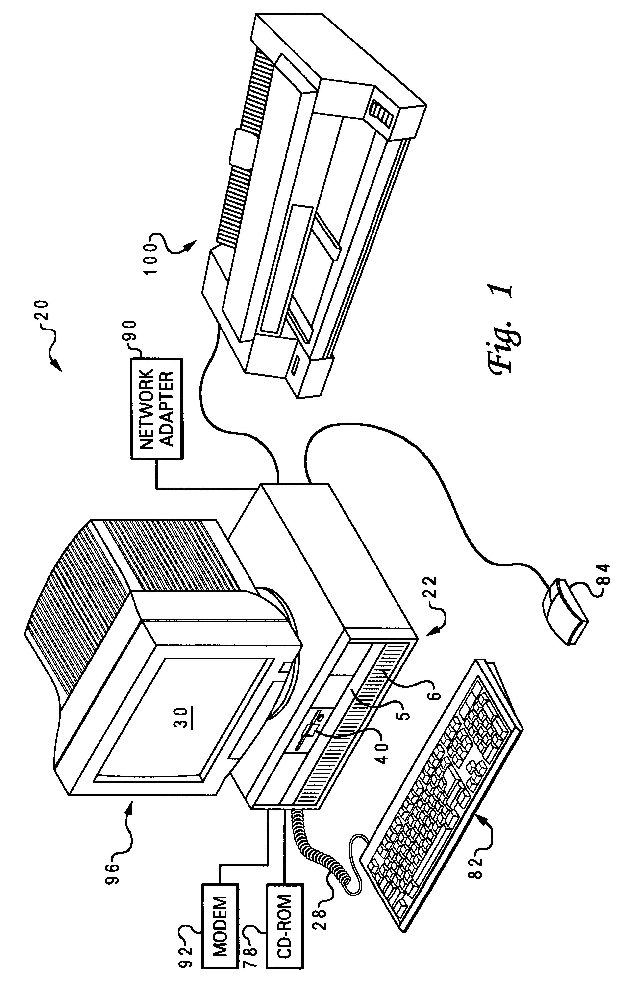
With reference now to the figures, and in particular with reference to FIG. 1, a data processing system 20 is shown in which the present invention can be implemented. The data processing system 20 includes processor 22, keyboard 82, and display 96. Keyboard 82 is coupled to processor 22 by a cable 28. Display 96 includes display screen 30, which may be implemented using a cathode ray tube (CRT), a liquid crystal display (LCD), an electroluminescent panel, or the like. The data processing system 20 also includes pointing device 84, which may be implemented using a track ball, a joy stick, touch sensitive tablet or screen, track path, or as illustrated a mouse. The pointing device 84 may be used to move a pointer or cursor on display screen 30. Processor 22 may also be coupled to one or more peripheral devices such as modern 92, CD-ROM 78, network adapter 90, and floppy disk drive 40, each of which may be internal or external to the enclosure or processor 22. An output device such as ...


PUM


Abstract

A method of providing an interconnection between one or more peripheral devices and a system bus of a computer system selectively establishes and removes a connection from a primary peripheral bus to a secondary peripheral buses, and determines a target from among the one or more peripheral devices when a bus bridge is a master of the primary peripheral bus, using an address decoder. Access to and from the primary peripheral bus is controlled using an arbiter to select a master for the primary peripheral bus from among the one or more peripheral devices, to allow both (i) selective establishing and removing of a connection from the primary peripheral bus to one of the secondary peripheral buses in response to the selection of the master, and (ii) isolating of the master prior to establishing the connection to the secondary peripheral bus.

Description

1. Field of the InventionThe present invention generally relates to computer systems, specifically to a method and apparatus for interconnecting various computer components (i.e., peripheral devices), and more particularly to a method and system that provides for "hot plugging" of adapter cards while increasing the load and expansion capabilities of the bus for such systems.2. Description of Related ArtA typical structure for a conventional computer system includes one or more processing units connected to a system memory device (random access memory or RAM) and to various peripheral, or input / output (I / O), devices such as a display monitor, a keyboard, a graphical pointer (mouse), and a permanent storage device (hard disk). The system memory device is used by a processing unit in carrying out program instructions, and stores those instructions as well as data values that are fed to or generated by the programs. A processing unit communicates with the other components by various mea...

Claims


Application Information

Patent Timeline
Patent Type & Authority Patents(United States)
IPC IPC(8): G06F13/40
CPCG06F13/4022
Inventor NEAL, DAN MARVINKELLEY, RICHARD ALLEN
Owner IBM CORP
Why Eureka
Try Eureka