Variable buoyancy cable

Inactive Publication Date: 2001-05-29
MARINE INNOVATIONS
View PDF28 Cites 86 Cited by
  • Summary
  • Abstract
  • Description
  • Claims
  • Application Information

AI Technical Summary

Problems solved by technology

There are a number of disadvantages associated with this type of design.
Furthermore, where operational needs dictate transition to another depth, a fixed buoyancy cable may have to be retrieved to the vessel and replaced with another cable, resulting in costly down time and the expense of acquiring and stowing additional cables onboard.
Another disadvantage associated with conventional fixed buoyancy marine seismic cables is the potential for the enclosed conductors to be damaged during deployment and retrieval from the cable vessel.
This bending in conjunction with large tensile forces can cause the elongated tension members enclosed within the cable jacket to compress some of the enclosed conductors against the portion of the cable jacket that is in contact with the sheave against each other, possibly resulting in damage to those conductors.
One

Method used


Image

  • Variable buoyancy cable
  • Variable buoyancy cable
  • Variable buoyancy cable

Examples


Embodiment Construction

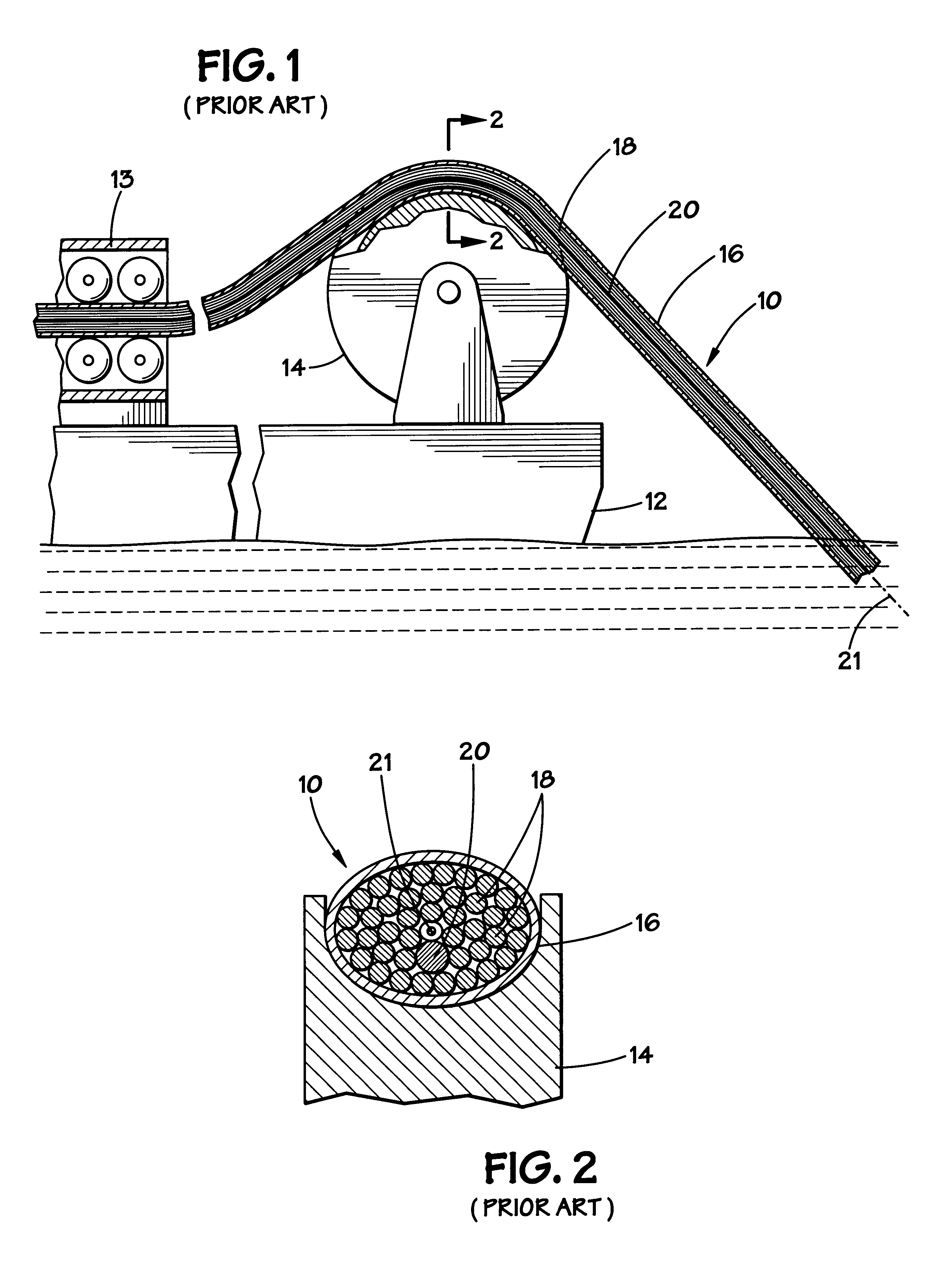
In the drawings described below, reference numerals are generally repeated where identical elements appear in more than one figure. FIG. 1 is a side view of a portion of an exemplary conventional seismic cable 10 that is deployed from a vessel 12. The cable 10 is deployed and retrieved from the vessel 12 with the aid of a linear cable engine 13 and a sheave 14 that is rotatably coupled to the vessel 12. Referring now also to FIG. 2, which is a sectional view of FIG. 1 taken at section 2--2, the cable 10 includes a flexible external jacket 16 that encloses a plurality of conductors 18. The conductors 18 are typically individually insulated conductor wires and cables, but also include such things as fiber optic cables and even fluid lines. The cable 10 undergoes significant tensile forces during deployment, retrieval and towing operations. Accordingly, a strength member 20, normally a wire rope or cable, is positioned inside the outer jacket 16 and nested among the conductors 18 along...


PUM


Abstract

A variable buoyancy cable is provided. In one aspect, the variable buoyancy cable includes a flexible sleeve that has an inner wall and an outer wall. A core is positioned in the sleeve and has a longitudinally disposed external channel with opposing first and second sidewalls. The channel and the inner wall of the flexible sleeve define a fluid passage for receiving a fluid to affect the buoyancy of the variable buoyancy cable. A slackened utility line is positioned in the channel and a fluid supply is coupled to the flexible sleeve and is operable to move fluid into and out of the fluid passage to selectively affect the buoyancy of the variable buoyancy cable. The core protects utility lines in the cable from damage due to ambient pressure and/or bending during deployment and retrieval. The buoyancy may be varied to suit various water conditions and mission requirements.

Description

1. Field of the InventionThis invention relates generally to marine seismic cables, and more particularly to a marine seismic cable with selectively controllable buoyancy.2. Description of the Related ArtOffshore oil and gas exploration and production operations frequently involve the repeated deployment of submerged cables for transmitting data signals and electrical power between various sensors and other electronic equipment and ship or land-based receiving stations. Marine seismic operations involve the static deployment of a submerged cable on the ocean bottom, or the suspension thereof between buoys or land structures. Other typical operations involve the towing of a submerged cable or "streamer" behind a ship. Still others employ a marine cable used as a tether for a Remotely Operated Vehicle ("ROV"). Such ROV set ups are now commonly used to conduct underwater inspections of various structures, such as oil rigs and the like.Most conventional marine seismic cables consist of ...

Claims


Application Information

Patent Timeline
IPC IPC(8): F16L1/14F16L1/24F16L11/12F16L11/133F16L1/12G01V1/16G01V1/20H01B7/12
CPCF16L1/14F16L1/24F16L11/133G01V1/201H01B7/12G01V2001/207
Inventor WOOTERS, TIMOTHY M.
Owner MARINE INNOVATIONS
Why Eureka
Try Eureka