
Commutator and method for manufacturing

Inactive Publication Date: 2001-06-05
KIRKWOOD INDS
View PDF14 Cites 9 Cited by
  • Summary
  • Abstract
  • Description
  • Claims
  • Application Information

AI Technical Summary

Benefits of technology

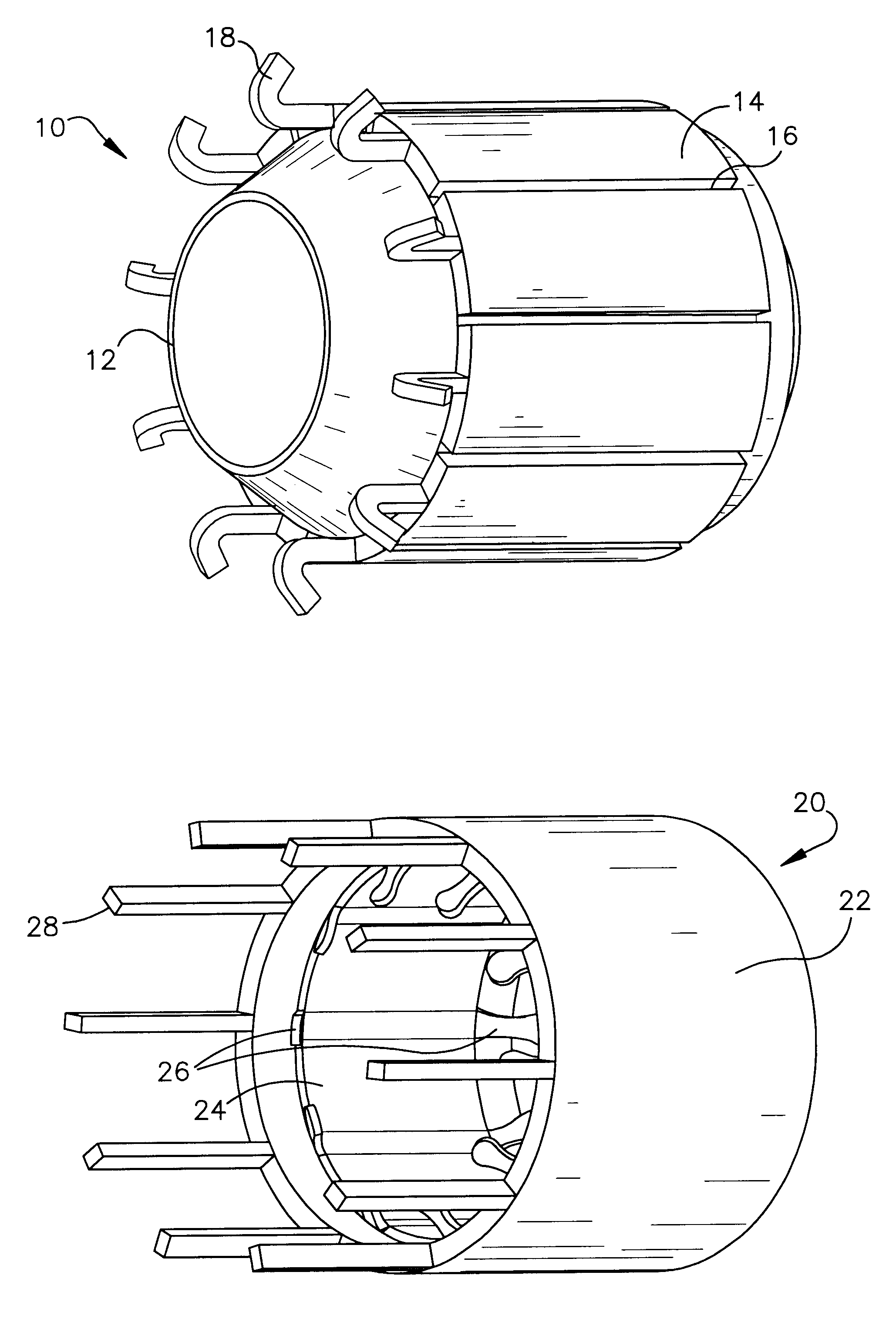
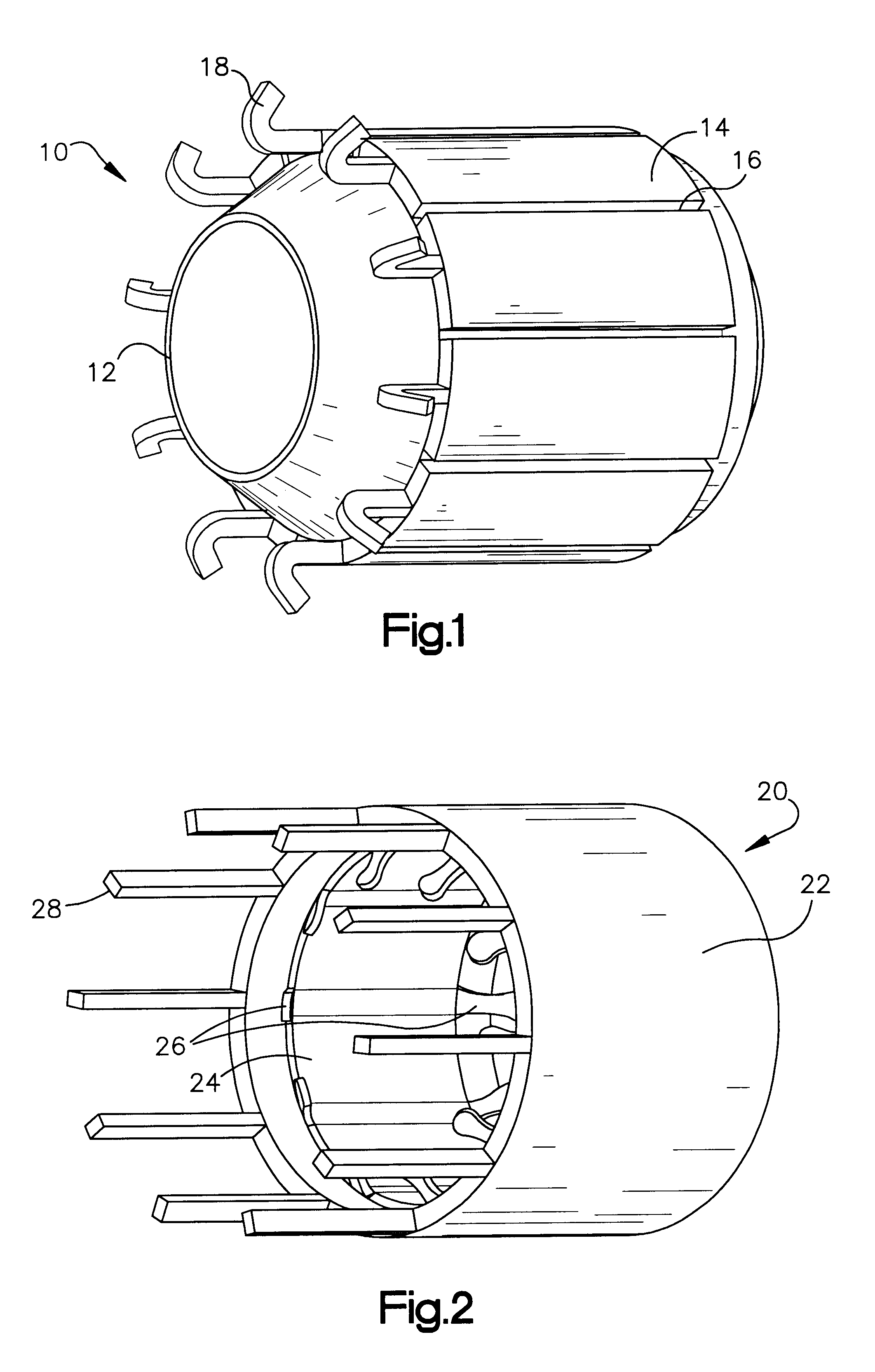
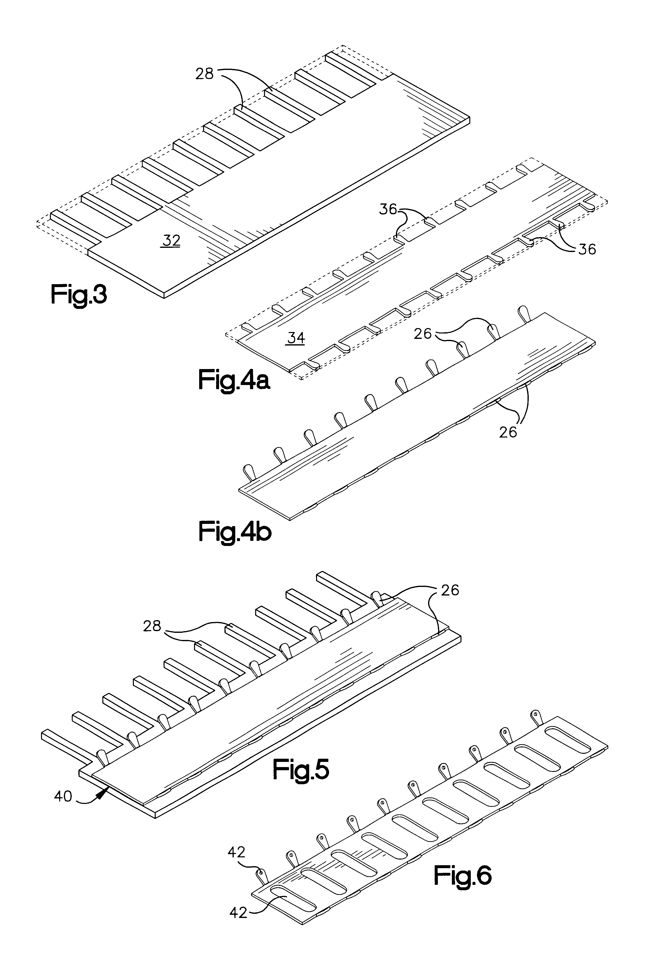
This invention provides commutators for electrodynamic machines, such as electric motors, that can be produced economically and efficiently and can be adapted to a wide variety of applications and requirements. These commutators comprise a cyclindrical shell of commutators bars, each of which has an outer layer with tangs extending from the outer layer and an inner layer with anchoring tabs or locking lugs extending therefrom. The commutating bars are typically produced from two strips of copper or other conductive metal. The inner layer may be formed of a thinner (or thinner and stronger) material, even a non-conductive material, but it is normally preferable to use two strips of copper to facilitate proper mechanical connection of the materials. The first strip, which is typically somewhat thicker than the second, is formed by punching or cutting so that partially formed tangs extend laterally from the side of the strip. The second strip is formed in a similar process to provide anchoring tabs extending from the sides of the strip. The second strip differs from the first in that the first strip normally only has tangs along one side of the strip, whereas the second strip normally has anchoring tabs along both sides. Also, the anchoring tabs typically extend at an angle to the plane of the second strip, whereas the partially formed tangs are generally co-planer with the first strip in the initial stages of production. As will be seen below, this invention simplifies fabrication of a wide variety of anchoring tabs, and the adaptation of the anchoring system to many different applications.
The use of two metallic strips facilitates adaptation of this commutator to a wide variety of motors and other dynamoelectric machines. The first or outer strip can be designed to provide requisite electrical conductivity, surface wear characteristics and tang strength. The second or inner strength can be designed to minimize the weight of the commutator while at the same time providing a secure connection between the commutating bars and the insulating hub.

Problems solved by technology

All of these techniques suffer from certain common problems.
They require expensive tooling, do not provide optimal dimensional control and do not allow desired balance between bar weight and locking lug positions.
This leads to excessive rejection rates, parts with excessive variations in dimensions or unbalanced centripetal forces, which in turn can lead to reduced performance and higher failure rates.

Method used


Image

  • Commutator and method for manufacturing
  • Commutator and method for manufacturing
  • Commutator and method for manufacturing

Examples


Embodiment Construction

The commutator illustrated in FIG. 1, referred to generally as 10, can be adapted to a wide variety of motors and other dynamoelectric machines, including automotive applications such as power windows, power seats, ABS systems and motor starters, and home appliances such as power tools, vacuum cleaners, mixers, blenders and washing machines. As will be seen below, the individual elements of this commutator can be modified to suit particular requirements of individual applications, which increases the field of use. This commutator is sturdy, dependable, and can be produced with common, uncomplicated forming tools, which makes commutators embodying this invention economical to produce.

As illustrated in FIG. 1, commutator 10 comprises a series of commutator bars 14, which are typically produced from copper alloys such as CDA 105 or CDA 107, supported by and spaced around the periphery of an insulating hub 12. The individual commutator bars are separated by gaps 16 which electrically in...


PUM

PropertyMeasurementUnit
Electrical conductoraaaaaaaaaa

Abstract

Commutators for electro-dynamic machines such as electric motors comprise a cylindrical shell of insulated commutators bars, each of which has an outer layer with tangs extending from the outer layer and an inner layer with anchoring tabs extending therefrom. The commutating bars are typically produced from two strips of copper or other conductive metal. The inner layer may be formed of a thinner but stronger material, even of a non-conductive material, but is normally preferable to use two strips of copper to facilitate fusion of the materials together. The first strip, which is typically somewhat thicker than the second, is formed by punching so that partially formed tangs extend laterally from the side of the strip. The second strip is formed in a similar process to provide anchoring tabs extending from the sides of the second strip. These commutators can be produced economically and efficiently and can be adapted to a wide variety of applications and requirements.

Description

TECHNICAL FIELDThis invention relates to commutators for electrodynamic machines such as motors and generators. More particularly, it relates to cylindrical commutators designed for economical, efficient and flexible production, and to methods for making these commutators.BACKGROUNDCommutators are routinely used to control the flow of electrical energy in rotating electrodynamic machines such as motors and generators. One typical commutator construction consists of a cylindrical ring of commutator bars supported by and positioned around an insulating hub. Tangs for electrical connections normally extend from one end of each commutator bar, and the bars are normally provided with inwardly extending anchoring bars to secure the bars to the insulating hub. The bars are normally slit from a cylindrical shell, produced by shaping a formed strip of metal into a cylindrical shell, molding the insulating hub inside the shell and slitting the shell to form the individual commutator bars.The ...

Claims


Application Information

Patent Timeline
IPC IPC(8): H01R43/08H01R43/06H02K13/04
CPCH01R43/08H02K13/04Y10T29/49011
Inventor CEFO, NEVRES
Owner KIRKWOOD INDS
Learn More