
Adaptive non-uniformity compensation using feedforwarding shunting

Inactive Publication Date: 2001-06-05
RAYTHEON CO
View PDF4 Cites 25 Cited by
  • Summary
  • Abstract
  • Description
  • Claims
  • Application Information

AI Technical Summary

Problems solved by technology

Unfortunately, these arrays, referred to as focal plane arrays are subject to anomalies such as detector to detector nonuniformity in sensitivity, gain / offset and fixed pattern noise.
While numerous techniques are known in the art for addressing detector to detector nonuniformity in sensitivity, gain / offset, fixed pattern noise continues to be problematic.
The non-uniform response causes the FPA output to be spatially varying even when illuminated by a uniform source.
But dynamic inputs, such as changing photon flux induced by dome heating, requires dynamic or adaptive non-uniformity compensation.
While nominally effective, this system limits the response time of the system.
In addition, conventional ADNUC systems are not designed to remove temporally correlated temporal noise.
Further, because FPNs are fixed on the focal plane and hence are temporally correlated, they present a more difficult false alarm problem than that presented by temporally uncorrelated temporal noise (TN).
In traditional ADNUC systems, the accumulated correction-offset terms will cause fixed-pattern artifacts, which may lead to a high number of false alarms for target detection by the missile tracking system (i.e., the "tracker").
Further, traditional systems do not remove hot-dome shading effects.
The heat on the dome creates a thermal background image which causes a filter mismatch in the tracker and thereby limits the performance of the system.

Method used


Image

  • Adaptive non-uniformity compensation using feedforwarding shunting
  • Adaptive non-uniformity compensation using feedforwarding shunting
  • Adaptive non-uniformity compensation using feedforwarding shunting

Examples


Embodiment Construction

Illustrative embodiments and exemplary applications will now be described with reference to the accompanying drawings to disclose the advantageous teachings of the present invention.

While the present invention is described herein with reference to illustrative embodiments for particular applications, it should be understood that the invention is not limited thereto. Those having ordinary skill in the art and access to the teachings provided herein will recognize additional modifications, applications, and embodiments within the scope thereof and additional fields in which the present invention would be of significant utility.

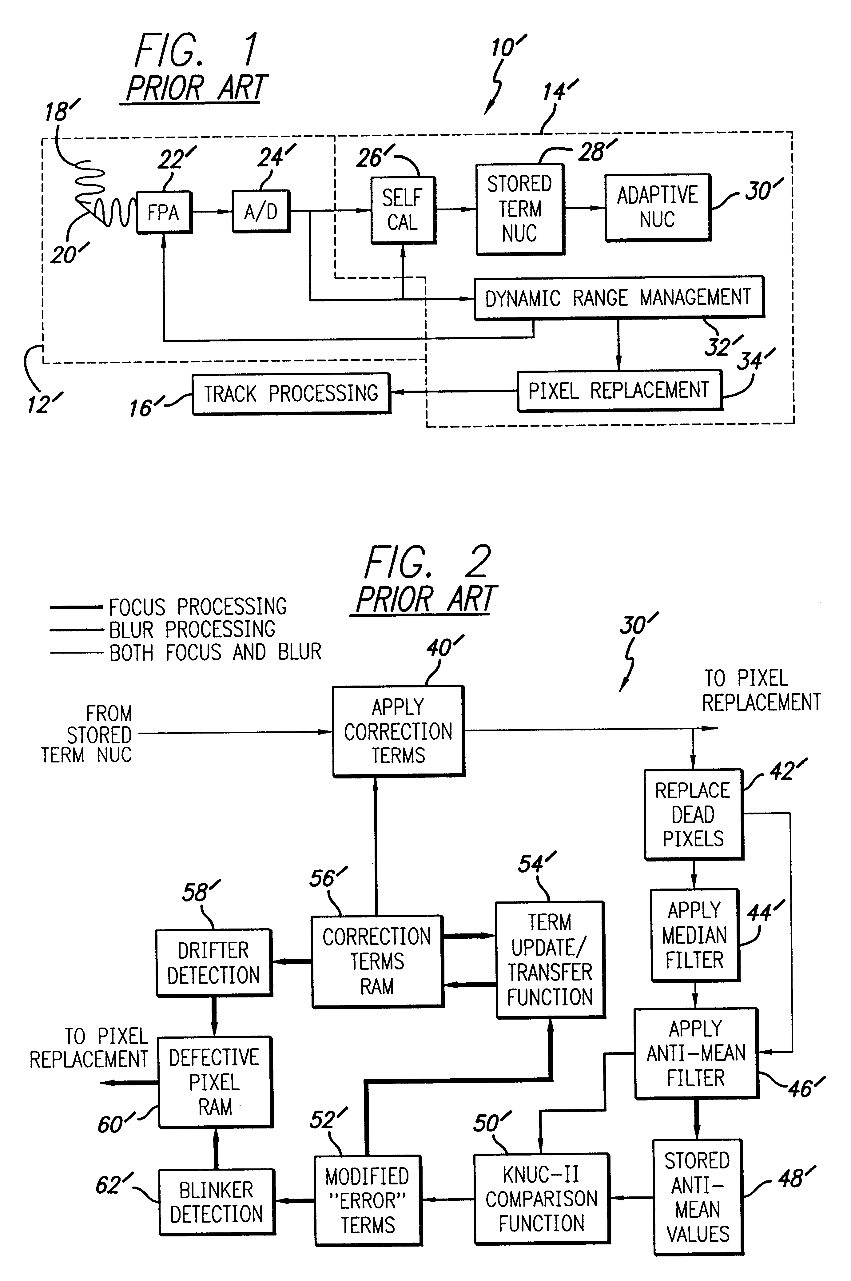
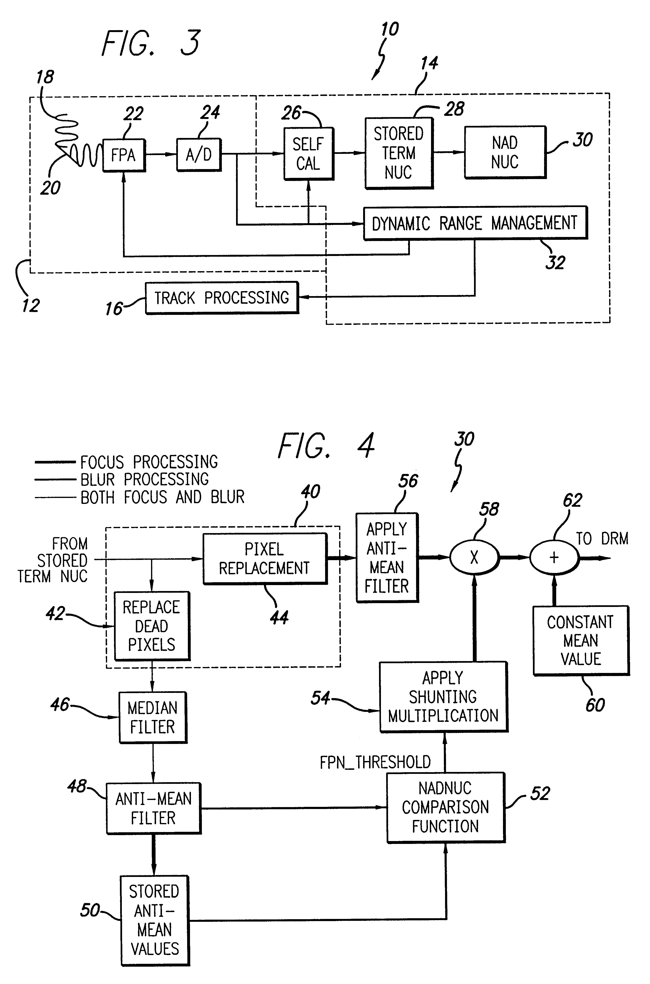
FIG. 1 is a block diagram of an infrared video processing system constructed in accordance with conventional teachings. The system 10' is implemented in hardware and software and includes an infrared camera 12'. The output of the video camera is processed by a video processing system 14' and a tracker 16'. Within the camera 12', infrared energy 18' from a scene ...


PUM


Abstract

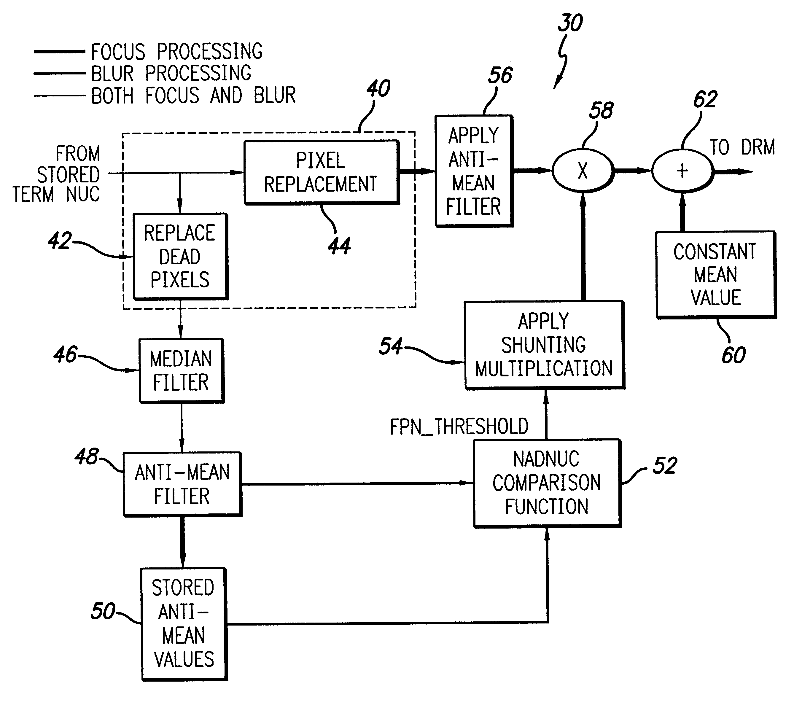
A system and method adapted for use with a focal plane array of electromagnetic energy detectors to receive first and second frames of image data from electromagnetic energy received from at least a portion of a scene. The first frame is a focused frame and the second frame is an unfocused frame. In a feed-forward path the system compares the first frame to the second frame and provides an error signal in response thereto. In a main path, the system multiplies at least a portion of the second frame of image data with the error signal to provide an noise error corrected output signal. In the preferred embodiment, the error signal is scaled prior to being multiplied by the second frame. An anti-mean (high pass) filter is provided to remove dome shading effects from the frames of image data. In the best mode, the anti-mean filter is disposed in the main path and blurred and focused outputs therefrom are weighted, averaged and stored. The weighted, averaged and stored focused frames are compared to the weighted, averaged and stored blurred frames to provide a fixed pattern noise error signal. A temporal noise error signal is identified from the weighted, averaged and stored focused frames. The fixed pattern and temporal noise error signals are fed forward and shunted from a current frame using multiplication or division. Thereafter, a constant mean value may be added to provide the output signal. Pixel replacement is consolidated into a single circuit and positioned prior to the anti-mean filter.

Description

1. Field of the InventionThe present invention relates to image and data processing systems and techniques. More specifically, the present invention relates to systems and techniques for adaptive non-uniformity compensation for focal plane arrays of infrared detectors and the like.2. Description of the Related ArtFocal plane arrays are used in military, astronomical and other applications. For example, in military applications, focal plane arrays are often used for target acquisition and tracking. The seekers of missiles often use arrays of image detectors sensitive to energy in the visible or (more typically) infrared portion of the electromagnetic spectrum. Unfortunately, these arrays, referred to as focal plane arrays are subject to anomalies such as detector to detector nonuniformity in sensitivity, gain / offset and fixed pattern noise. While numerous techniques are known in the art for addressing detector to detector nonuniformity in sensitivity, gain / offset, fixed pattern noise...

Claims


Application Information

Patent Timeline
IPC IPC(8): H04N5/217H04N5/33H04N5/365
CPCH04N5/2353H04N5/33H04N5/365H04N23/73H04N25/67
Inventor CHEN, HAI-WENBRAUNREITER, DENNIS C.SCHMITT, HARRY A.
Owner RAYTHEON CO
Learn More