
Process for generating electric power

a technology of electric power generation and process, which is applied in the direction of steam engine plants, machines/engines, mechanical equipment, etc., can solve the problems of high capital cost of steam turbine generating system per kwh generating capacity, gas turbines cost less than steam turbine units per kwh of power, and are less energy efficient than steam turbine units

Inactive Publication Date: 2001-06-12
WYLIE ROGER
View PDF5 Cites 35 Cited by
  • Summary
  • Abstract
  • Description
  • Claims
  • Application Information

AI Technical Summary

Problems solved by technology

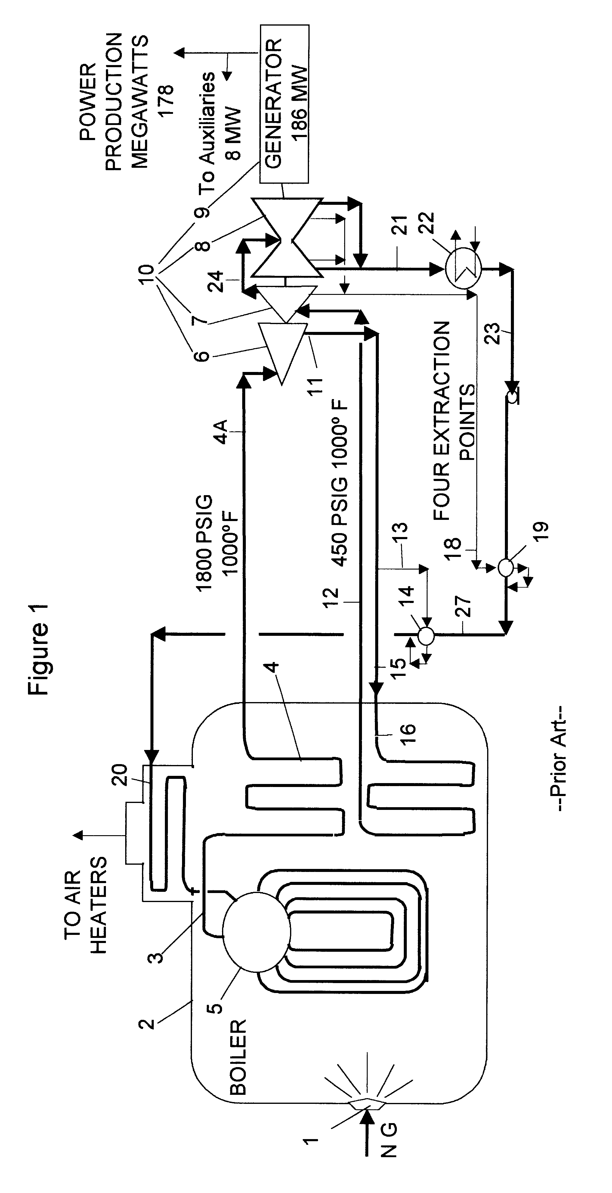
The capital cost of steam turbine generating systems per KWH generating capacity is high.
Gas turbines cost less than steam turbine units per KWH of power capacity but they are less energy efficient than steam turbine units.

Method used


Image

  • Process for generating electric power
  • Process for generating electric power
  • Process for generating electric power

Examples


example 2

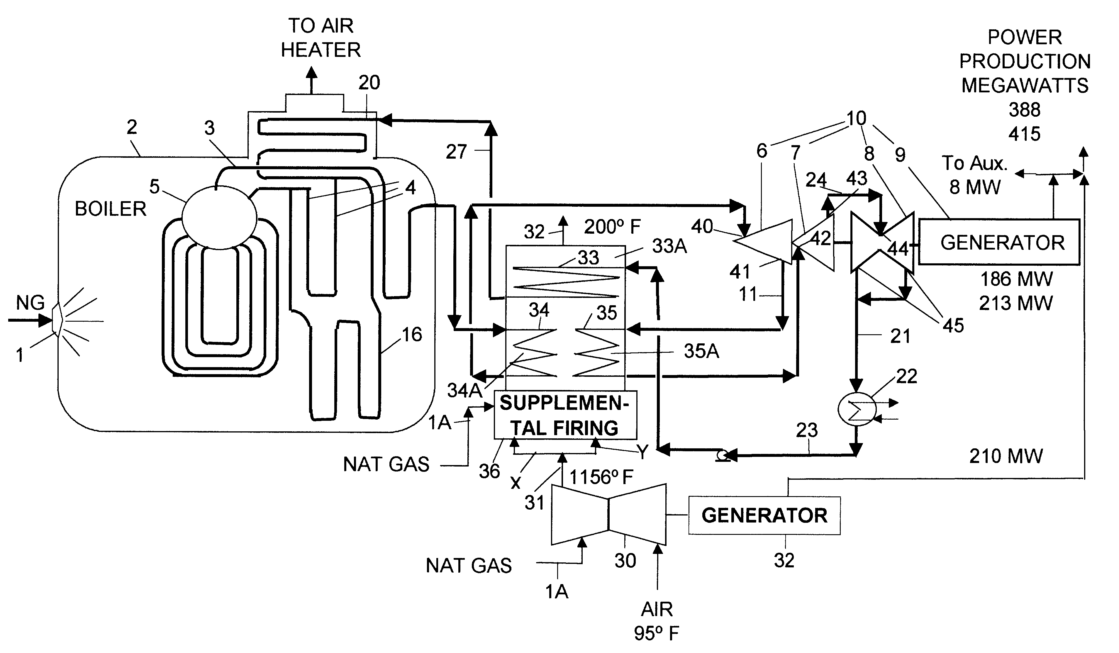
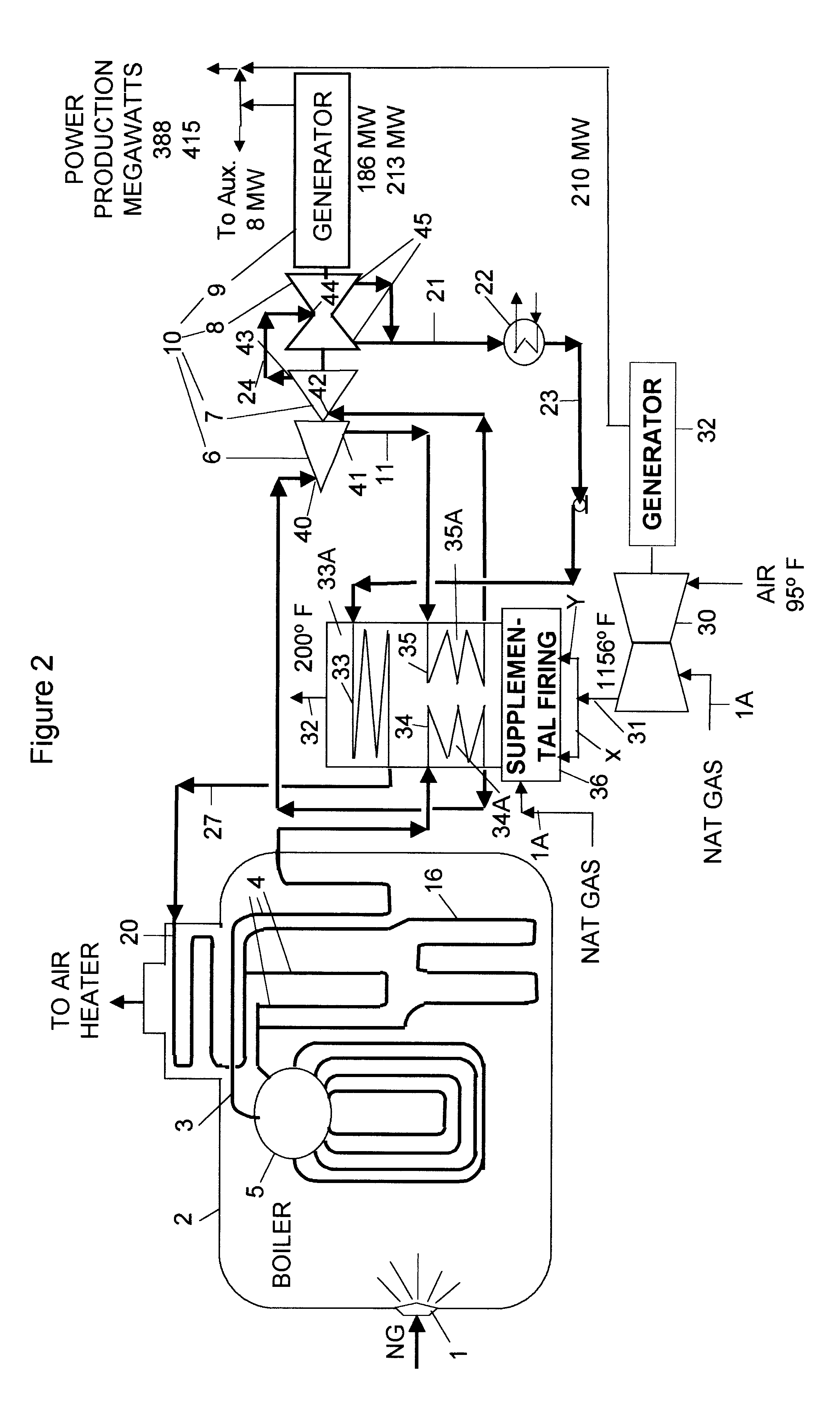
Assuming the same efficiency parameters and auxiliary power demands as in the conventional prior art power system of Example 1, the combined net power output of the steam turbine unit plus the gas turbine unit of the present invention as shown in FIG. 2 is 388 MW. The overall heat rate is 6,714 BTU (LHV) / KWH; this is 24% lower than the heat rate for the conventional prior art power system of Example 1.

EMBODIMENT USING SUPPLEMENTAL FOSSIL FUEL FIRING

example 3

Referring again to FIG. 2, during periods of peak power demand, supplemental natural gas 1A is fired in the furnace zone 36. The supplemental firing permits the operator to increase the high pressure steam rate produced by the boiler 2 to 1,241,000 lbs. per hour, and the power output of steam turbine generator 9 using the additional steam increases the power output to 418 KWH, providing an additional 27 KWH of power. The heat rate of this additional power is 8,600 BTU (LHV) / KWH. This Is too high to be economical for continuous base load power but is cost effective during periods of peak power demand. Accordingly, supplemental firing is used to provide peak power during periods of high power demand.

DESCRIPTION OF PREFERRED EMBODIMENT FOR BOILERS HEATED BY NUCLEAR REACTORS

FIG. 3 is an embodiment of the process of the present invention that is preferred for boilers heated by nuclear reactors. Nuclear boilers operate at lower pressure e.g. about 600 psig. The process includes a nuclear ...

example 4

The total power output from the steam turbine 6 and the two gas turbines 30 is 1,933 MW. The overall heat rate for the 625 MW of incremental power produced by burning natural gas is 6,200 BTU (LHV) / KWH. In a conventional process, without the gas turbines 11, the 14 million lbs per hour of 600 psig saturated steam produced by the nuclear boiler generates only 1308 MW of power in the steam turbine-generator, providing a heat rate about 12,000 BTU (LHV) / KWH


PUM


Abstract

A process for a steam turbine-generator system that includes a boiler and a train of steam turbines and a gas turbine generator system. Exhaust gas from the gas turbine superheats the high pressure steam produced by the boiler in the steam generator system and reheats a steam side stream extracted at an intermediate point on the steam turbine train in the steam generator system after which the reheated steam side stream is fed back into the steam turbine train downstream of the extraction point. Further, the exhaust gas preheats a steam condensate stream formed by condensing the exhaust steam from the downstream steam outlet on the steam turbine train after which the preheated condensate is recycled back to the boiler. The gas turbine exhaust gas superheats the high pressure steam and reheats the steam side stream before it preheats the steam condensate stream. A second embodiment of the invention includes firing supplemental fossil fuel to provide additional heat to superheat the high pressure steam, and / or to reheat the intermediate pressure steam stream, and / or to preheat the steam condensate stream.

Description

This invention relates to generation of electric power in large stationary power plants.Modern electric power generating stations include steam turbine power generating systems comprised of a boiler, steam turbines, and an electric generator. The boiler produces high pressure saturated steam that is usually superheated in tubes fired in the boiler. The steam turbines are connected in series trains with steam flowing from turbine to turbine. The high pressure superheated stream from the boiler is fed into the inlet of the upstream steam turbine. Steam pressure and temperature decrease as the steam moves downstream through the turbine train. The steam turbines are connected to a drive shaft that turns the electric generator producing electric power. The steam boiler is fired with a fossil fuel, e.g. natural gas, coal or lignite, or is heated by a nuclear reactor. Modern fossil fuel fired boilers typically operate at pressures between 1800 and 2400 psig and some operate above the criti...

Claims


Application Information

Patent Timeline
Patent Type & Authority Patents(United States)
IPC IPC(8): F01K23/10F02C6/18
CPCF01K23/103F02C6/18Y02E20/16
Inventor WYLIE, ROGER
Owner WYLIE ROGER
Learn More