Valve control unit for a fuel injection valve

a fuel injection valve and valve control technology, applied in the direction of fuel injection apparatus, charge feed system, combustion engine, etc., can solve the problems of large volume of fuel inside the first valve control chamber to be displaced, and the injected quantity of fuel cannot be sufficiently minimized

Inactive Publication Date: 2001-06-12
ROBERT BOSCH GMBH
View PDF10 Cites 12 Cited by
  • Summary
  • Abstract
  • Description
  • Claims
  • Application Information

AI Technical Summary

Benefits of technology

The valve control unit according to the invention, for a fuel injection valve for a common rail injector operates to minimize the quantity of preinjected fuel and to increase the movement speed of the valve control piston.Whereas the end member in the prior art is comprised of one part, this invention is comprised of two parts: an inner structural member and an outer structural member. The two structural members can be moved in relation to each other and are connected to the valve control piston. When the outlet conduit is opened and fuel escapes from the first valve control chamber into the second valve control chamber, the two structural members of the end member can move inside the first valve control chamber. During the preinjection, the two structural members move together by a small stroke, whereas during the main injection, only the inner structural member moves by an additional stroke. This results in the fact that during the preinjection, due to the movement of the valve control piston, a greater volume of fuel must first be displaced from the first valve control chamber by the end member (inner and outer structural member). Therefore, the valve control piston can only execute a small stroke. The preinjected quantity of fuel is therefore kept low. In contrast, during the main injection, only the inner structural member of the end member moves so that a smaller volume of fuel has to be displaced from the first valve control chamber. The valve control piston can therefore be moved with an increased movement speed and a larger stroke.In a preferred embodiment, the first valve control chamber has a first stop to limit the movement of the outer structural member in the direction of the second valve control chamber and has a second stop to limit the movement of the inner structural member in the direction of the second valve control chamber. Through the embodiment of the two stops, the movement of the structural members inside the first valve control chamber is executed in a definite and reproducible manner. A uniform small quantity of fuel is always preinjected, without impairing the increased movement speed during the main injection.Other advantages and advantageous embodiments of the subject of the invention can be inferred from the specification, the drawing, and the claims.

Problems solved by technology

Disadvantageously, a large-volume end member connected to the valve control piston must be moved inside the first valve control chamber.
Due to the stroke motion of the valve member, during the preinjection, the injected quantity of fuel cannot be sufficiently minimized.
During the main injection, it is likewise disadvantageous that a large volume of fuel inside the first valve control chamber must be displaced by the end member when the valve control piston moves away from the injection opening.

Method used


Image

  • Valve control unit for a fuel injection valve
  • Valve control unit for a fuel injection valve

Examples


Embodiment Construction

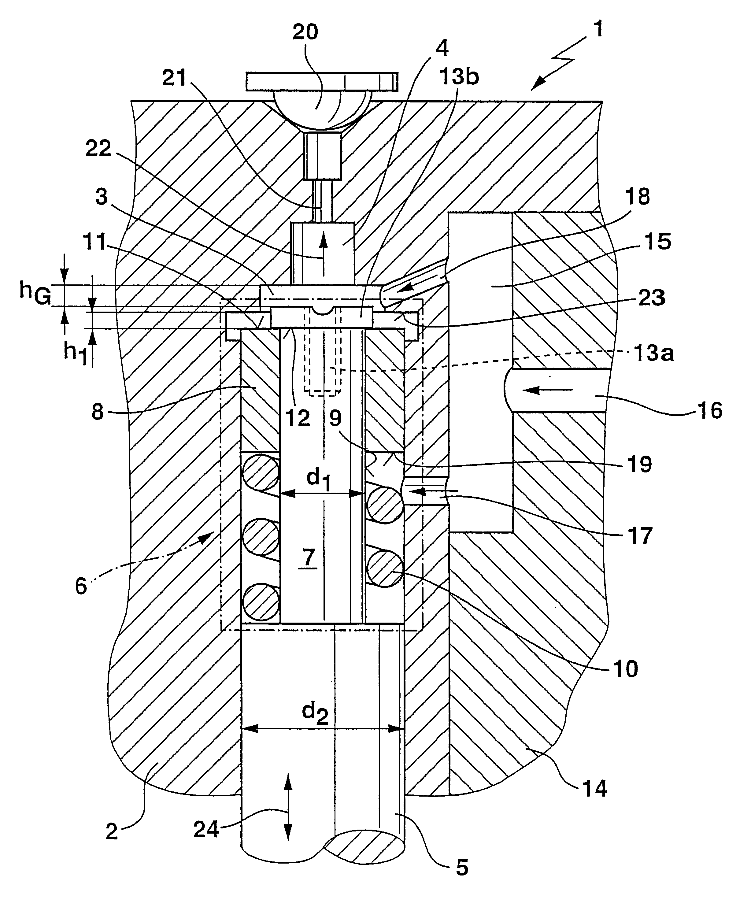
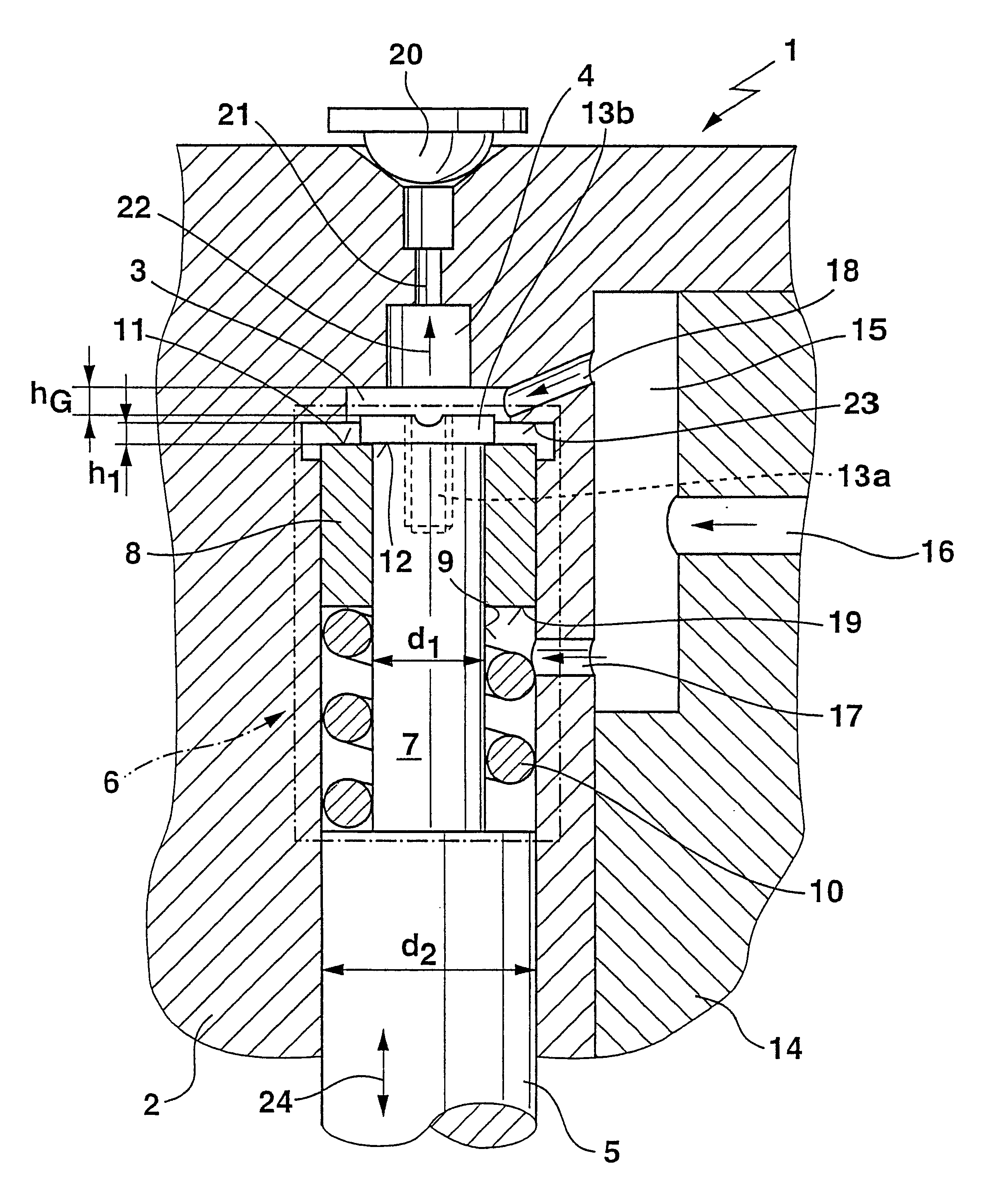
The exemplary embodiment of a valve control unit 1 is disposed in a rest position in which the injection opening, which is not shown in the FIGURE, is closed.

In order to open and close the injection opening, a housing body 2 of the valve control unit 1, as a central subject, has a first valve control chamber 3 and a second valve control chamber 4. The change of the pressure conditions inside the valve control chambers 3 and 4 can influence the movement of a valve control piston 5. The valve control piston 5 has an end member 6 which is comprised of an inner structural member in the form of a piston section 7 and an outer structural member in the form of a control ring 8. The control ring 8, which is concentric to the piston section 7, is movably disposed on an outer circumference surface 9 of the piston section 7. A compression spring 10 presses the control ring 8 with an annular face 11 against an opposing face 12. A fastening plate 13b is connected to the piston section 7 by means...


PUM


Abstract

A valve control unit for a fuel injection valve includes a housing body with two valve control chambers that continuously communicate with each other. An end member of a movable valve control piston can be moved inside the first valve control chamber and the first valve control chamber communicates with an inlet conduit for fuel. The second valve control chamber communicates with an outlet conduit that can be closed by a ball valve. The end member is comprised of an inner structural member and an outer structural member that can move in relation to each other. In the movement of the valve control piston, only the outer structural member is moved for a preinjection of fuel and the inner structural member is moved for the main injection. The quantity of preinjected fuel can be further minimized while an increased movement speed of the valve control piston is simultaneously possible during the main injection.

Description

PRIOR ARTThe invention is based on a valve control unit for a fuel injection valve for a common rail injector.A valve control unit of this type is known, for example, from EP 0 661 442 A1.Valve control units of this type are provided for controlling the injection process in the preinjection and main injection of fuel (diesel fuel) in common rail injectors. The valve control unit influences the impingement of pressure on the one end of a movably supported valve control piston of the valve control unit. The other end of the valve control piston can act on an injector needle so that the injector needle either closes an injection opening or permits fuel to escape from the injection opening.With the known valve control unit, the impingement of pressure on the valve control piston is carried out by changing the pressure conditions inside a first valve control chamber, which communicates with a high pressure reservoir (common rail) by way of a supply conduit. When the valve control unit is...

Claims


Application Information

Patent Timeline
Patent Type & Authority Patents(United States)
IPC IPC(8): F02M45/08F02M45/00F02M47/02F02M63/00F02M47/00
CPCF02M45/08F02M47/027F02M2200/505
Inventor BOECKING, FRIEDRICH
Owner ROBERT BOSCH GMBH
Why Eureka
Try Eureka