Process of injection molding a foamable plastic composition

Inactive Publication Date: 2001-06-12
JNC CORP
View PDF6 Cites 6 Cited by
  • Summary
  • Abstract
  • Description
  • Claims
  • Application Information

AI Technical Summary

Benefits of technology

a) filling completely a molten foamable plastic composition into a cavity, while redu

Problems solved by technology

In such prior processes, however, the problem remains that the molded article of good appearance is not produced.
Since the cavity volume is enlarged at the same time as the injection, a cell collapse occurs at the surface portion of the molded article and the surface having a non- or low-foamed, dense cell structure is not obtained.
In case of using a mold having the cavity structure with a thin-wall at the position away from the gate, it is difficult to completely fill the mold.
In case of using the mold having the cavity structure with a thin-wall at the position away from the gate (e.g. the mold for the molded article having a large flat area, ribs and bosses) and a conventional molding machine, it is difficult to maintain the pressure of the foamable plastic so as to prevent it from foaming.
However, the problem remains on economy.
Further, the prior processes have the problems that in the production of the molded article having a large flat area, a thin-walled r

Method used


Image

  • Process of injection molding a foamable plastic composition
  • Process of injection molding a foamable plastic composition
  • Process of injection molding a foamable plastic composition

Examples


Example

Composition

This composition was prepared by mixing 100 parts by weight of a propylene homopolymer having a melt flow rate of 2.5 g / 10 minutes based on test condition 14 of JIS K 7210 (230.degree. C., 21.18N) and a melting point of 165.degree. C. with 3 parts by weight of azodicarbonamide (ADCA) under agitation using a tumbling mixer.

Injection Molding Machine

There was used an injection molding machine provided with a cylinder of 90 mm screw diameter and a mold clamping mechanism with a maximum mold clamping force of 650T.

Mold

A mold was used for the manufacture of the molded article shown in FIGS. 1 and 2. The mold has cross ribs and bosses at four corners and a box type cavity having the size of 410 mm in length, 295 mm in width and 50 mm in height, in which a parting part of the mold is of a fitting type and the volume of the cavity is changeable at the moving location of the mold. A pressure sensor for the measurement of the internal pressure was arranged on the mold surface in con...

Example

EXAMPLE 1

The molding was performed using the composition, injection molding machine and mold as mentioned above and further setting the cylinder temperature of the molding machine at 230.degree. C. and the coolant temperature of the mold at 70.degree. C., by the following procedure.

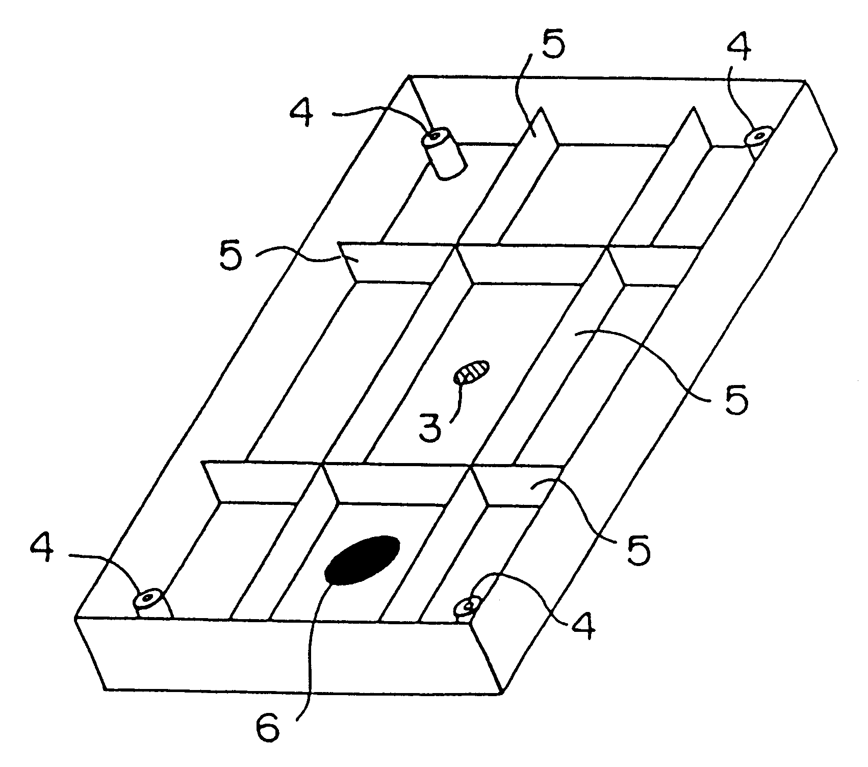
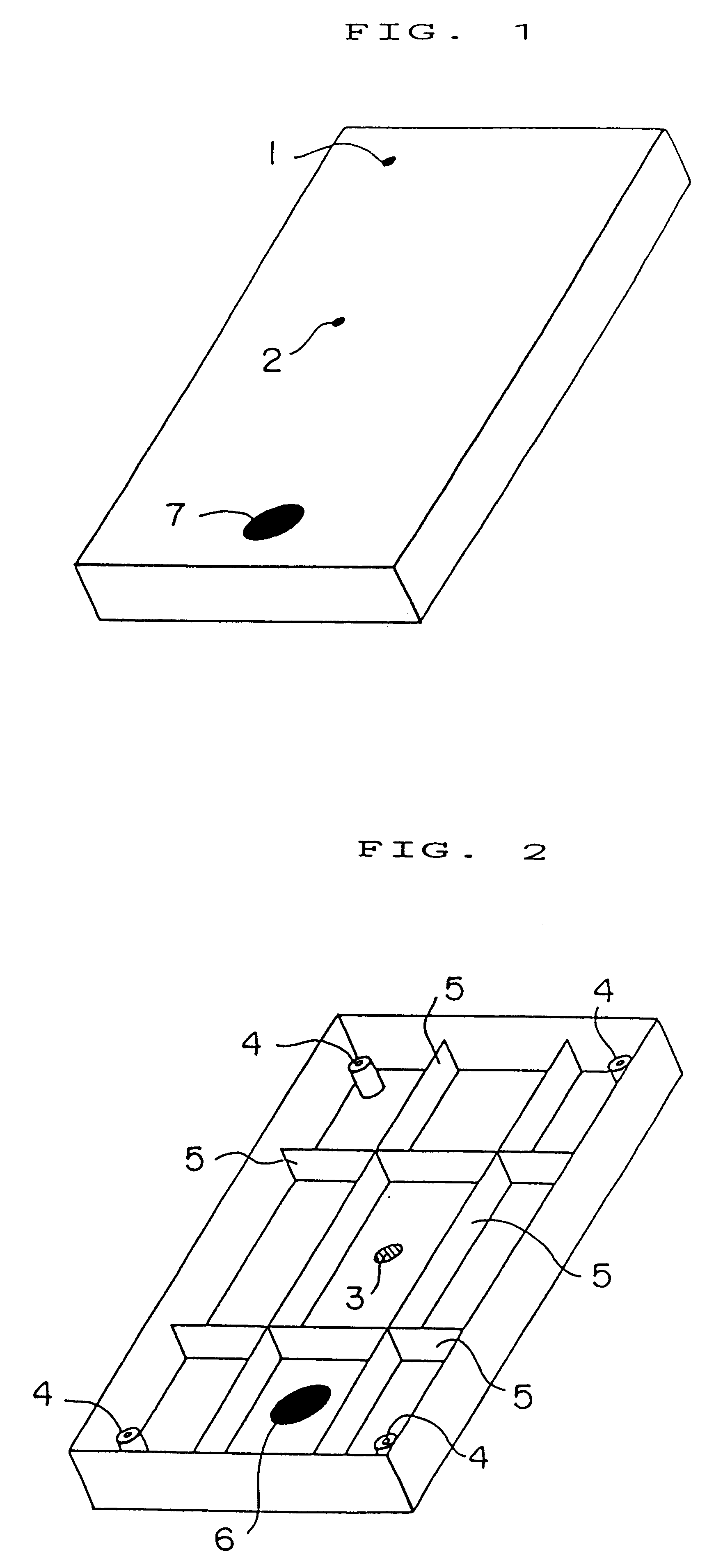
(i) 420 g of the composition was injected into a cavity measuring 590 cc in volume and 2.7 mm in a space between the mold surface (movable mold) in contact with the location indicated at 7 in FIG. 1 and the mold surface (stationary mold) in contact with the location indicated at 6 in FIG. 2, which is abbreviated hereafter as "the thickness at the top portion". The injection was completed after 3 seconds.

(ii) In the course of injection, the reduction of the cavity volume was started 1.5 second after injection and completed after 2 seconds so that the thickness at the top portion of the cavity became 1.7 mm and the volume became 470 cc.

(iii) After completion of the reduction in cavity volume, cooling was co...

Example

EXAMPLE 2

The molding was performed by a similar procedure as mentioned in Example 1, except that the injection in step (i) was conducted into a cavity having the volume of 712 cc and the thickness of 3.7 mm at the top portion. There was obtained a molded article having the size of 410 mm in length.times.295 mm in width.times.52.8 mm in height and the volume of 869 cc.

The characteristics and maximum pressure on molding (measured value) of the resultant molded article are shown in Table 1.


PUM

PropertyMeasurementUnit
Percent by massaaaaaaaaaa
Weightaaaaaaaaaa
Compositionaaaaaaaaaa

Abstract

A process of injection molding a foamable plastic composition which comprises filling completely a molten foamable plastic composition into a cavity, while reducing a volume of the cavity in the middle of injection or immediately after injection; cooling the composition to the state wherein a solidified layer in contact with a mold surface mingles with a molten inside layer; enlarging the volume of the cavity to that of the desired molded article; and after further cooling, removing the molded plastic foam article. This molded article comprises a layer having a non- or low-foamed, dense structure on the surface and a high-foamed layer at the inside, and has a light weight, good appearance and stiffness.

Description

This invention relates to a process of injection molding a foamable plastic composition. More particularly, the invention relates to a process of injection molding a molded plastic foam article having a light weight, good thermal insulating properties and stiffness, the surface of the molded article comprising a layer having a non- or low-foamed, dense cellular structure and the inside of the molded article comprising a fine, uniform high-foamed layer.As a process of injection molding foamable plastics, Japanese Patent Kokai Sho 62-246710 discloses an injection molding process wherein a mold to be connected to the injection port of an injection molding machine consists of a stationary mold part and a movable mold part, a cavity formed therebetween can be enlarged and reduced by moving the movable mold part, and before a foaming agent is injected into the mold from the injection molding machine, the cavity is enlarged to a predetermined size by making the movable mold part go backwar...

Claims


Application Information

Patent Timeline
IPC IPC(8): B29C44/02B29C44/04B29C44/08
CPCB29C44/0407B29C44/0415B29C44/083B29C2045/565
Inventor YOSHIZAKI, MICHIOHONDA, KOICHI
Owner JNC CORP
Why Eureka
Try Eureka