Apparatus with voraxial separator and analyzer

a separator and analyzer technology, applied in the direction of centrifuges, filtration separation, separation processes, etc., can solve the problems of water contamination, loss of precious drinking water, and economic burden of separation of such contaminants

Inactive Publication Date: 2001-06-19
SCHLUMBERGER TECH CORP
View PDF6 Cites 25 Cited by
  • Summary
  • Abstract
  • Description
  • Claims
  • Application Information

AI Technical Summary

Problems solved by technology

Major sources of drinking water contamination are chemicals and particulate matter mingling with cleaning water used during metal finishing and other chemical etching processes.
Separation of such contaminants represents an economic burden and more often a loss of precious drinking water.
A limitation of this prior separator, however, has been the prospect of turbulence within the flow stream following angular acceleration and radial component stratification, resulting from transition to lower rotational speed, causing some intermixing of stratified layers.

Method used


Image

  • Apparatus with voraxial separator and analyzer
  • Apparatus with voraxial separator and analyzer
  • Apparatus with voraxial separator and analyzer

Examples


Embodiment Construction

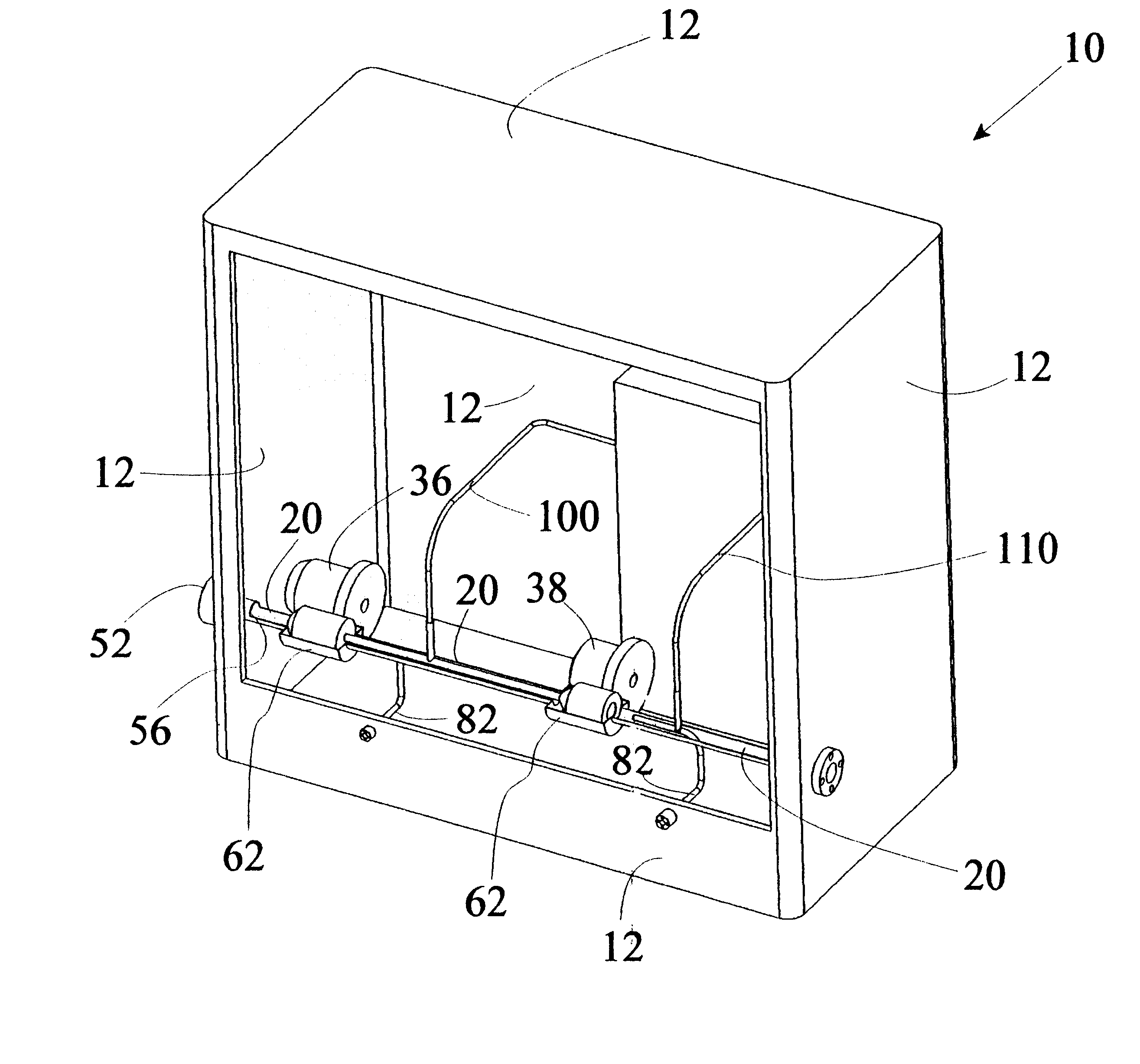
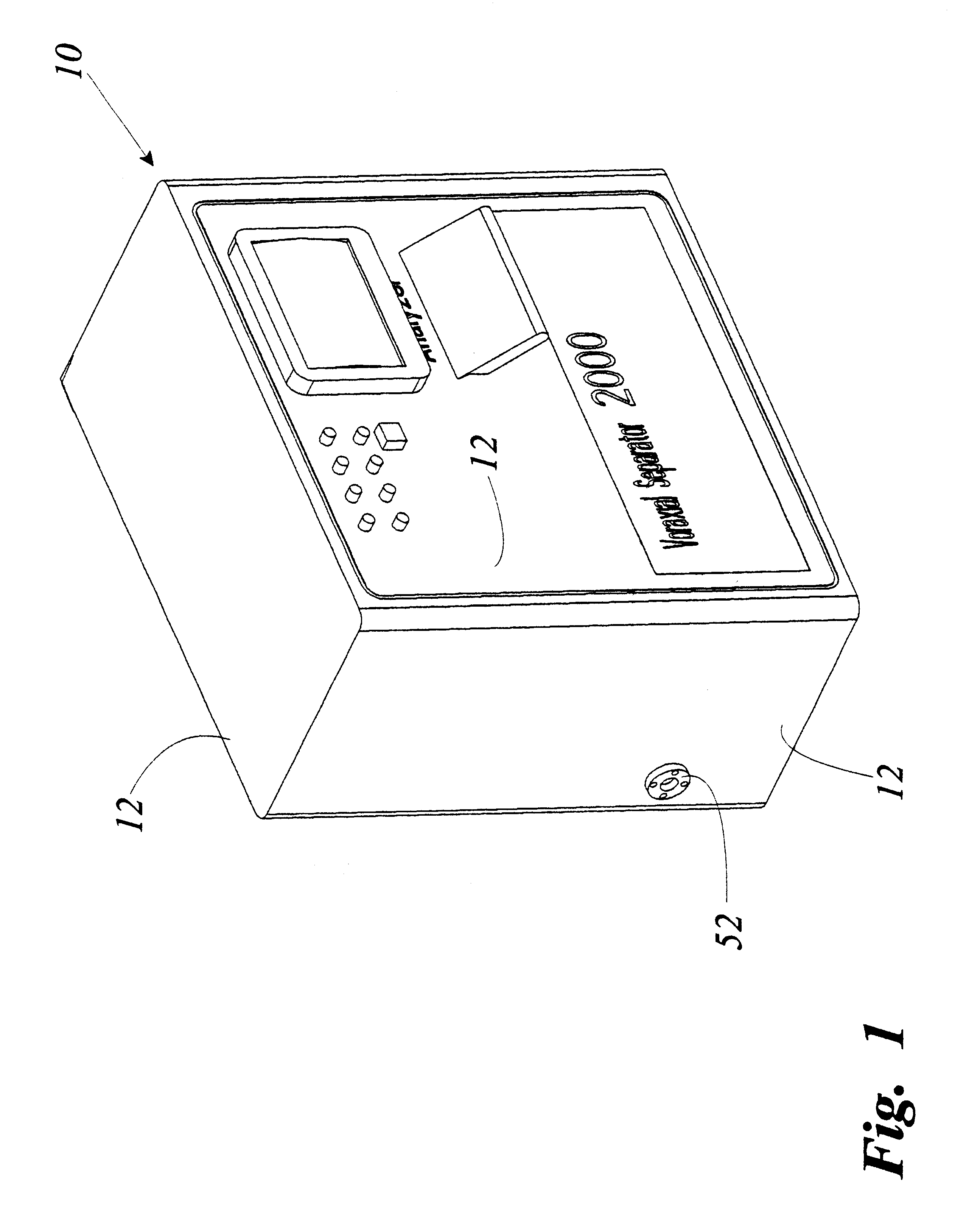
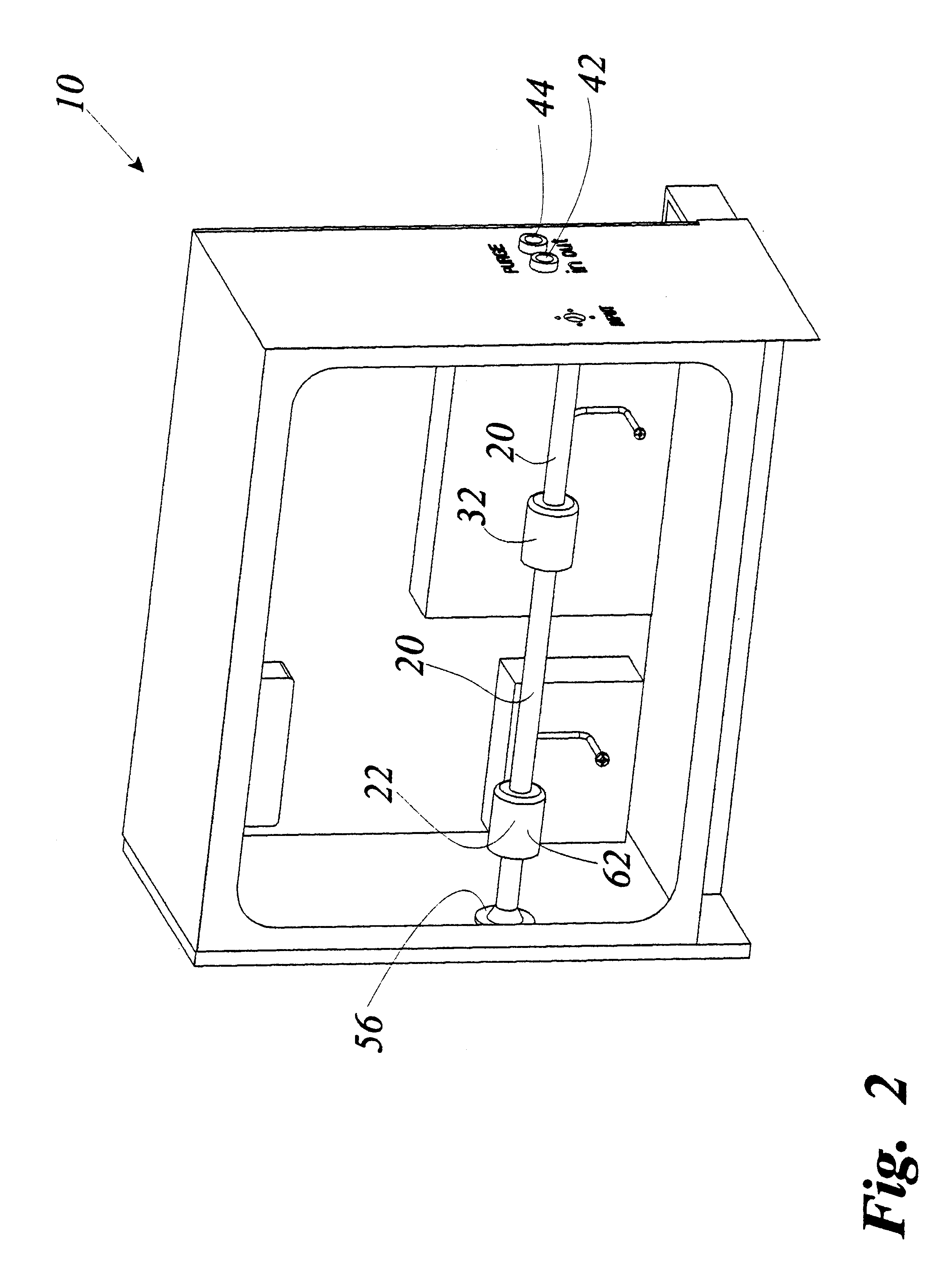
Referring to FIGS. 1-14, a voraxial separator and analyzer apparatus 10 is disclosed. Apparatus 10 includes a composite fluid passing voraxial tube 20 containing a first set of rotation vanes referred to as rotation acceleration vane member 22 connected to vane rotation means 24. The set of rotation acceleration vane member 22 is oriented to deliver angular acceleration to a composite fluid within the tube 20 about the longitudinal axis of the tube 20 to a given rotational speed at which the component fluids making up the composite fluid separate into radially stratified layers. The set of rotation acceleration vane member 22 also deliver linear, axial velocity to the composite fluid to propel the composite fluid through the tube 20 while it is being separated. A second set of rotation vanes referred to as rotation maintenance vane member 32 as shown in FIGS. 2 and 4, is inventively provided within the tube 20 downstream of the set of acceleration vane member 22. Rotation maintenanc...


PUM

PropertyMeasurementUnit
densityaaaaaaaaaa
rotational velocityaaaaaaaaaa
accelerationaaaaaaaaaa

Abstract

A voraxial separator and analyzer apparatus includes a composite fluid passing tube having a tube upstream segment and a tube downstream segment; a rotation acceleration vane structure rotationally mounted within the tube upstream segment and being oriented to deliver angular acceleration to a composite fluid within the tube about the longitudinal axis of the tube for separating the fluid into radially stratified component layers within the tube in the order of component density and to propel the fluid toward and through the tube downstream segment; an acceleration vane drive mechanism drivably connected to the rotation acceleration vane structure; a rotation maintenance vane structure rotationally mounted within the tube downstream segment and being oriented to deliver angular acceleration to a composite fluid within the tube about the longitudinal axis of the tube for maintaining the rotational velocity of the fluid imparted by the rotation acceleration vane structure against friction losses; and a maintenance vane drive mechanism drivably connected to the rotation maintenance vane structure.

Description

1. Field of the InventionThe present invention relates generally to the field of oil reclamation devices. More specifically the present invention relates to a voraxial separator and analyzer apparatus for separating and reclaiming oil from water, such as in the aftermath it of a tanker ship oil spill, and for separating and reclaiming pure water from industrial contaminants. The apparatus includes a composite fluid passing tube containing a first set of rotation vanes referred to as rotation acceleration vanes connected to vane rotation means. The set of rotation acceleration vanes is oriented to deliver angular acceleration to a composite fluid within the tube about the longitudinal axis of the tube to a given rotational speed at which the component fluids making up the composite fluid separate into radially stratified layers according to their densities. A second set of rotation vanes referred to as rotation maintenance vanes is inventively provided within the tube downstream of t...

Claims


Application Information

Patent Timeline
Patent Type & Authority Patents(United States)
IPC IPC(8): B01D17/02B04B5/12B04B5/00B01D17/028B01D17/038
CPCB01D17/0217B04B5/12
Inventor DI BELLA, ALBERTOANTHONY, MICHAEL M.
Owner SCHLUMBERGER TECH CORP
Why Eureka
Try Eureka