Variable focal-length lens system

a lens system and variable technology, applied in the field of zoom lenses, can solve the problems of affecting portability, affecting the performance of the lens, and affecting the length of the overall lens,

Inactive Publication Date: 2001-06-19
NIKON CORP
View PDF11 Cites 20 Cited by
  • Summary
  • Abstract
  • Description
  • Claims
  • Application Information

AI Technical Summary

Problems solved by technology

However, there has been the problem that an increase in zooming ratio is accompanied by an increase in focal length, causing the length of the overall lens to become large and adversely affecting portability.
Furthermore, with the positive-positive-negative three-group-type lens, due to the fact that above a zooming ratio of three the lateral magnification of the negative lens group becomes large when in the extreme telephoto state, it is necessary that the positional accuracy of the several lens groups be made extremely precise, with the result that lens performance deteriorates markedly because of the influence of stopping precision.
In particular, because of the need to increase the lateral magnification of the negative lens group in order to achieve small size, it has been difficult to simultaneously achieve both small size and high performance.
With the positive-negative-positive-negative four-group-type lens, because of the increased number of movable lens groups the lateral magnification of the negative lens group arranged nearest to the image plane is relaxed i.e., is lessened when in the extreme telephoto state, and, while the zooming ratio might be high and it may be possible to achieve small size and high performance, it has not been possible to achieve adequate wide-angle performance.
While the positive-negative-positive-positive-negative five-group-type lens better permits attainment of high zooming ratio and small size while maintaining high performance as compared with the aforementioned four-group-type lens, because of the large widths of the several lens groups in the direction of the optical axis it has been difficult to achieve improved camera portability.
This is because the second lens group, with its negative refracting power, displays a strong diverging action, and so arranging the aperture stop at a location far removed from the second lens group would result in inability to satisfactorily correct for off-axial aberration produced at the second lens group when in the extreme wide-angle state, and moreover, arranging the aperture stop to the object side of the second lens group would result in inability to satisfactorily correct for off-axial aberration produced at the third lens group and fourth lens group due to the fact that off-axial light beams made to diverge at the second lens group would then pass through the third lens group and fourth lens group at points far removed from the optical axis.
While shortening of the overall length of the lens can easily be accomplished by strengthening the refracting powers of the several lens groups, if a prescribed range of focal lengths is to be maintained there will be a sharp increase in the required stopping precision of the lens, especially when in the extreme telephoto state, causing increased complexity in lens barrel construction and consequently impairing portability.
However, overshortening of the back-focus distance when in the extreme wide-angle state will cause off-axial light beams passing through the fifth lens group to become too far removed from the optical axis, leading to excessive lens diameter, so it is desirable that a suitable value be used therefor.
To achieve high-speed autofocus function it is essential that the mechanical work (=weight.times.travel) performed by the focusing group(s) be made small, but in the case of the (A) FF method, lens diameter is extremely large, making it unsuitable for autofocus applications.
If the second lens group and the fourth lens group are made to move in integral fashion, then causing a change in the distance between the second lens group and the fourth lens group during retraction of the lens barrels within the camera main body when the camera is to be carried would invite complexity in lens barrel structure and would tend to nullify the effect of causing the second lens group and the fourth lens group to move in integral fashion.
Exceeding the upper limit of conditional expression (1), and causing the width from the second lens group to the fourth lens group to become large, will cause the thickness of the camera main body when carried to become large, impairing portability.
Conversely, below the lower limit of conditional expression (1), variation in the lateral magnification of the fifth lens group during changes in the positional state of the lens will become too large, preventing satisfactory correction of fluctuations in off-axial aberrations accompanying changes in the positional state of the lens.
Above the upper limit of conditional expression (3), portability is impaired because of increased overall lens length when in the extreme telephoto state.
Conversely, below the lower limit thereof, off-axial light beams passing through the first lens group will become too far removed from the optical axis when in the extreme telephoto state, leading to increased lens diameter.
Above the upper limit of conditional expression (4), positive distortion produced at the fifth lens group becomes extremely large, and satisfactory correction of positive distortion becomes impossible.
Conversely, below the lower limit thereof, adequate back-focus distance when in the extreme wide-angle state cannot be ensured.
Above the upper limit of conditional expression (5), travel of the third lens group during short-distance focusing becomes extremely large, leading to increased complexity in the focusing drive mechanism.
Conversely, below the lower limit thereof, fluctuation in axial aberrations produced during short-distance focusing becomes extremely large.
If this position control precision varies widely depending on whether the lens is in the extreme wide-angle state or the extreme telephoto state, then this will create problems such as delayed third lens group control speed, inability to attain a prescribed level of optical performance, and so forth.
Because the amount of travel required for focusing varies as a function of lateral magnification, exceeding the upper limit of conditional expression (6) will cause the degree of lens position control precision necessary to achieve a prescribed level of optical performance to become far greater when in the extreme telephoto state than when in the extreme wide-angle state, resulting in the problems mentioned above.
Conversely, below the lower limit thereof, the required degree of position control precision when in the extreme wide-angle state will become extremely high, resulting in the problems mentioned above.

Method used


Image

  • Variable focal-length lens system
  • Variable focal-length lens system
  • Variable focal-length lens system

Examples


first embodiment

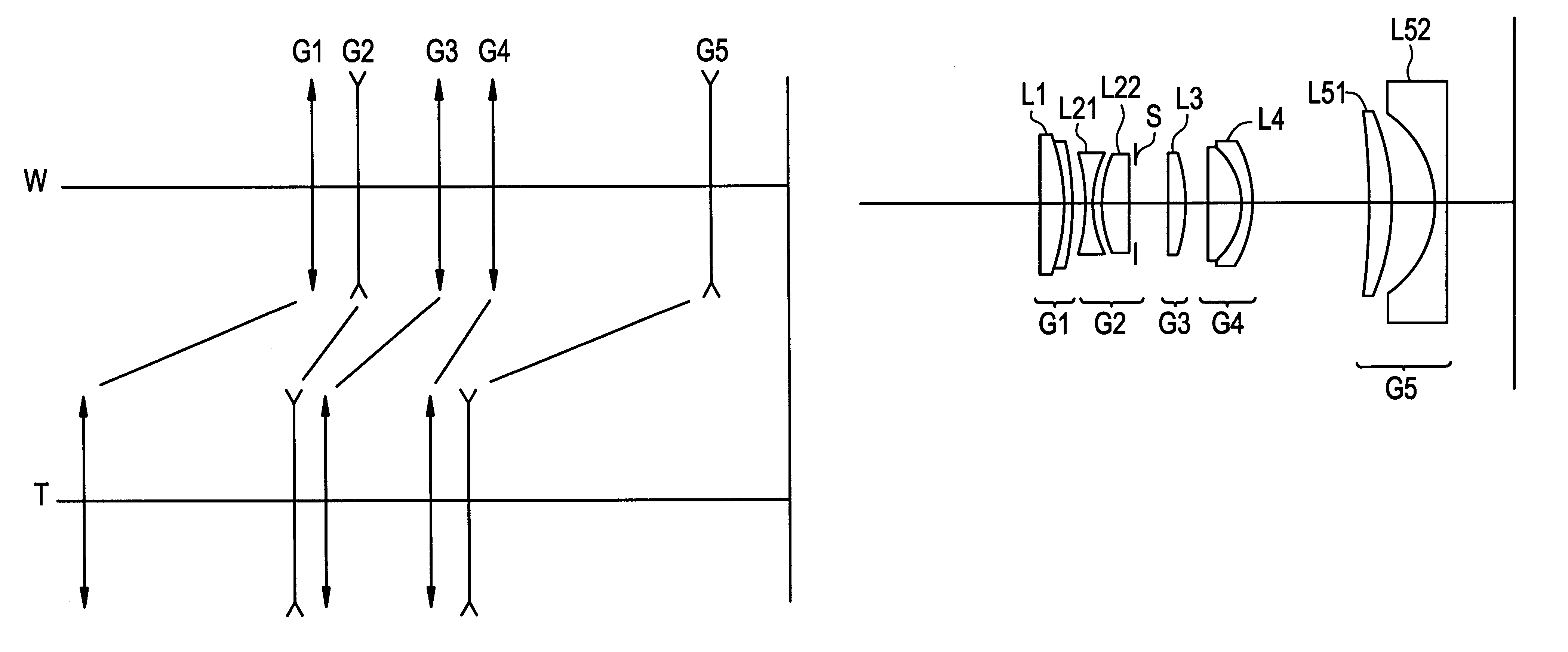
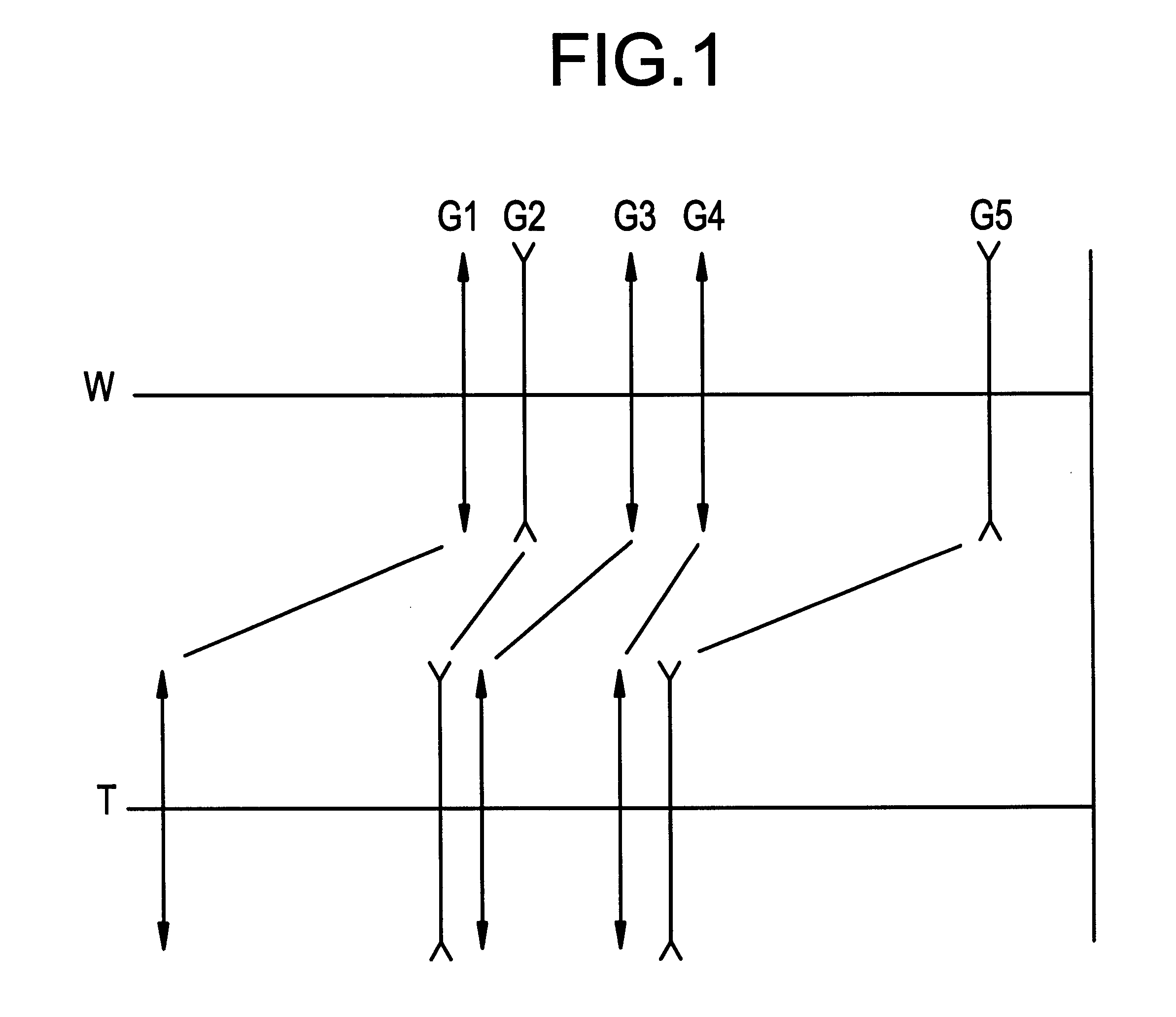
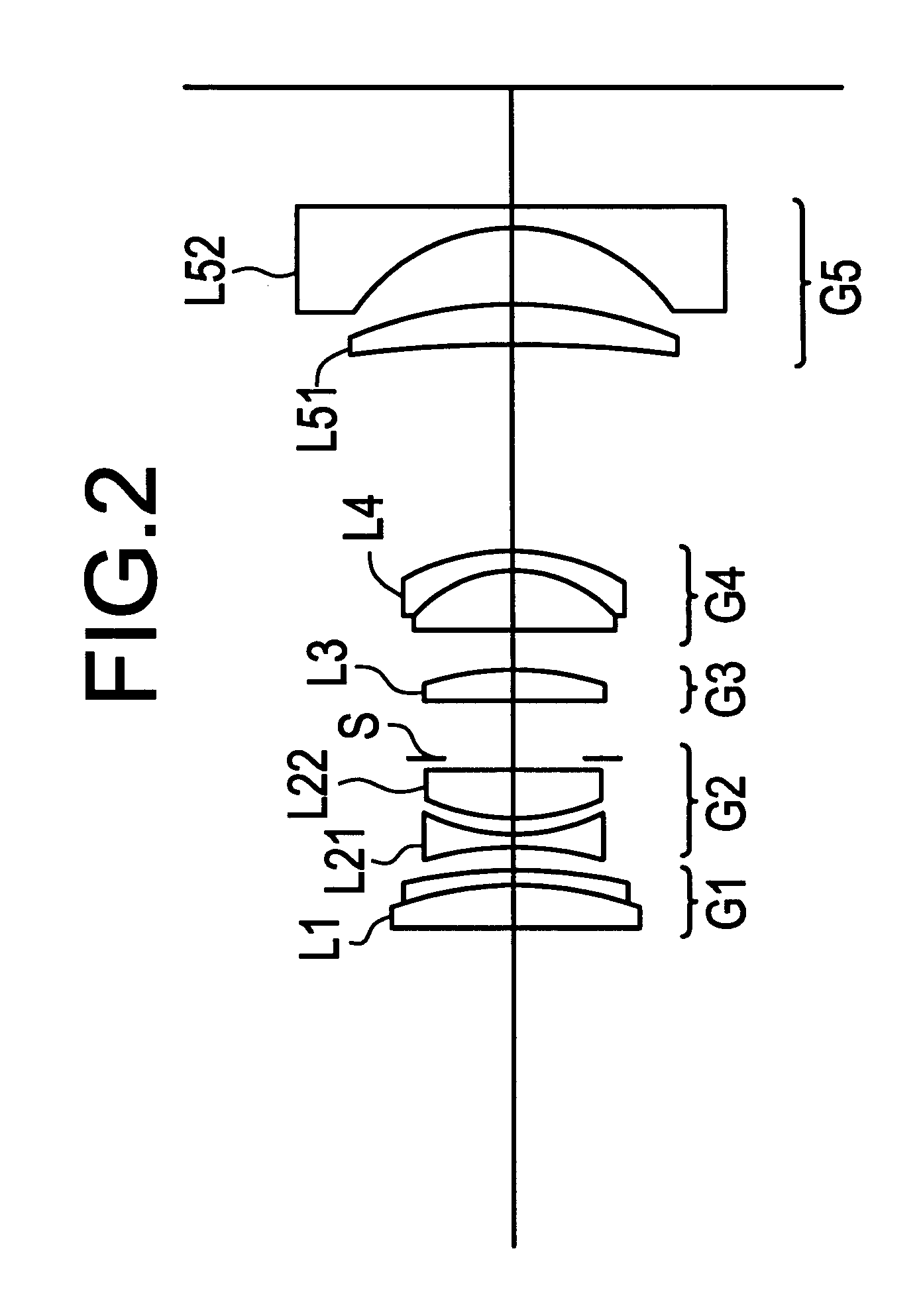
FIG. 2 is a drawing showing the constitution of the lenses in a first embodiment of the present invention, wherein, in order from the object side, a first lens group G1 consists of a cemented positive lens L1 containing a biconvex lens and a negative meniscus lens which presents a concave surface toward the object side, a second lens group G2 consists of a biconcave lens L21 and a biconvex lens L22, a third lens group G3 consists of a biconvex lens L3, a fourth lens group G4 consists of a cemented positive lens L4 containing a biconvex lens and a negative meniscus lens which presents a concave surface toward the object side, and, a fifth lens group G5 consists of a positive meniscus lens L51 which presents a concave surface toward the object side and a negative meniscus lens L52 which presents a concave surface toward the object side.

An aperture stop S is arranged between the second lens group G2 and the third lens group G3, and this aperture stop moves in integral fashion with the ...

second embodiment

FIG. 9 is a drawing showing the constitution of the lenses in a second embodiment of the present invention, wherein, in order from the object side, a first lens group G1 consists of a cemented positive lens L1 containing a biconvex lens and a negative meniscus lens which presents a concave surface toward the object side, a second lens group G2 consists of a biconcave lens L21 and a positive lens L22 which presents a convex surface toward the object side, a third lens group G3 consists of a biconvex lens L3, a fourth lens group G4 consists of a cemented positive lens L4 containing a biconvex lens and a negative meniscus lens which presents a concave surface toward the object side, and a fifth lens group G5 consists of a positive meniscus lens L51 which presents a concave surface toward the object side and a negative meniscus lens L52 which presents a concave surface toward the object side.

An aperture stop S is arranged between the second lens group G2 and the third lens group G3, and...

third embodiment

FIG. 16 is a drawing showing the constitution of the lenses in a third embodiment of the present invention, wherein, in order from the object side, a first lens group G1 consists of a cemented positive lens L1 containing a biconvex lens and a negative meniscus lens which presents a concave surface toward the object side, a second lens group G2 consists of a biconcave lens L21 and a positive lens L22 which presents a convex surface toward the object side, a third lens group G3 consists of a biconvex lens L3, a fourth lens group G4 consists of a cemented positive lens L4 containing a biconvex lens and a negative meniscus lens which presents a concave surface toward the object side, and a fifth lens group G5 consists of a positive meniscus lens L51 which presents a concave surface toward the object side and a negative meniscus lens L52 which presents a concave surface toward the object side.

An aperture stop S is arranged between the second lens group G2 and the third lens group G3, and...


PUM


Abstract

A variable-focus lens system that is small in size and permits attainment of high zooming ratio while maintaining high performance. In order from the object side, there are therein a first, positive lens group; a second, negative lens group; a third, positive lens group; a fourth, positive lens group; and a fifth, negative lens group; all of the lens groups move toward the object side in such fashion as to cause the distance between the first and second lens groups to increase, the distance between the second and third lens groups to decrease, the distance between the third and fourth lens groups to increase, and the distance between the fourth and the fifth lens groups to decrease, when the positional state of the lens changes from the extreme wide-angle state to the extreme telephoto state. At this time, the second lens group and the fourth lens group move in integral fashion during a change in the positional state of the lens, an aperture stop is arranged between the second and third lens groups, and the aforesaid third lens group moves during short-distance focusing. Suitable ranges for the widths of the second through fourth lens groups are defined by means of conditional expressions.

Description

The present invention pertains to a variable-focal-length lens system, and in particular pertains to a variable-focal-length lens system that is small in size and that has a high zooming ratio.BACKGROUND OF THE RELATED ARTIn recent years, zoom lenses have come into common use in photographic optical systems for use in still cameras, video cameras, and the like; in particular, cameras employing so-called high-zoom lenses wherein zooming ratios are in excess of three are rapidly becoming standard equipment.Particularly with integral-lens-type cameras, wherein the photographic optical system is integral with the camera main body, importance is placed on portability, and there have accordingly been a variety of proposals pertaining to zoom lenses suitable for applications permitting reduction in size and weight.Specifically, positive-positive-negative three-group-type lenses (consisting of, in order from the object side, a positive lens group, a positive lens group, and a negative lens ...

Claims


Application Information

Patent Timeline
Patent Type & Authority Patents(United States)
IPC IPC(8): G02B15/163G02B15/173G02B15/20
CPCG02B15/173G02B15/145113
Inventor OHTAKE, MOTOYUKI
Owner NIKON CORP
Why Eureka
Try Eureka