Thinning razor

a razor and thinning technology, applied in the field of thinning razors, can solve the problems of affecting the awkwardness of the push button means in relation to the cutting means, and the discomfort of holding and operating the device, so as to achieve the effect of doubling the working life of the blad

Inactive Publication Date: 2001-06-26
TOKYO RIKI
View PDF12 Cites 37 Cited by
  • Summary
  • Abstract
  • Description
  • Claims
  • Application Information

AI Technical Summary

Benefits of technology

The relationship between the driving member and the sliding member as described above provides for a thinning razor having a single-edged blade with the non-exposed segments of the sharp edge becoming exposed when merely pushing the exposed surface of the driving member, thereby doubling the working life of the blade.

Problems solved by technology

a) the prospect of quick and safe blade replacement,
b) economic usage of the entire blade,
c) alternative methods of use, and
d) a convenient grip.
Although the working life of the blade in U.S. Pat. No. 3,805,381 is doubled, the mechanism of the push button means in relation to the means for cutting is awkward, in that the user must focus on a small part of the device in order to precisely align the arrow with the second index.
Also, its unusual design especially of the tapered handle makes holding and operating the device rather discomforting.
Nevertheless, production costs and subsequent retail prize of both replaceable razors described above are considerable high, on top of which, the device disclosed in Japanese Unexamined Patent Publication No. 090060 / 1999 does not even use the entire length of its blade.

Method used


Image

  • Thinning razor
  • Thinning razor
  • Thinning razor

Examples


Embodiment Construction

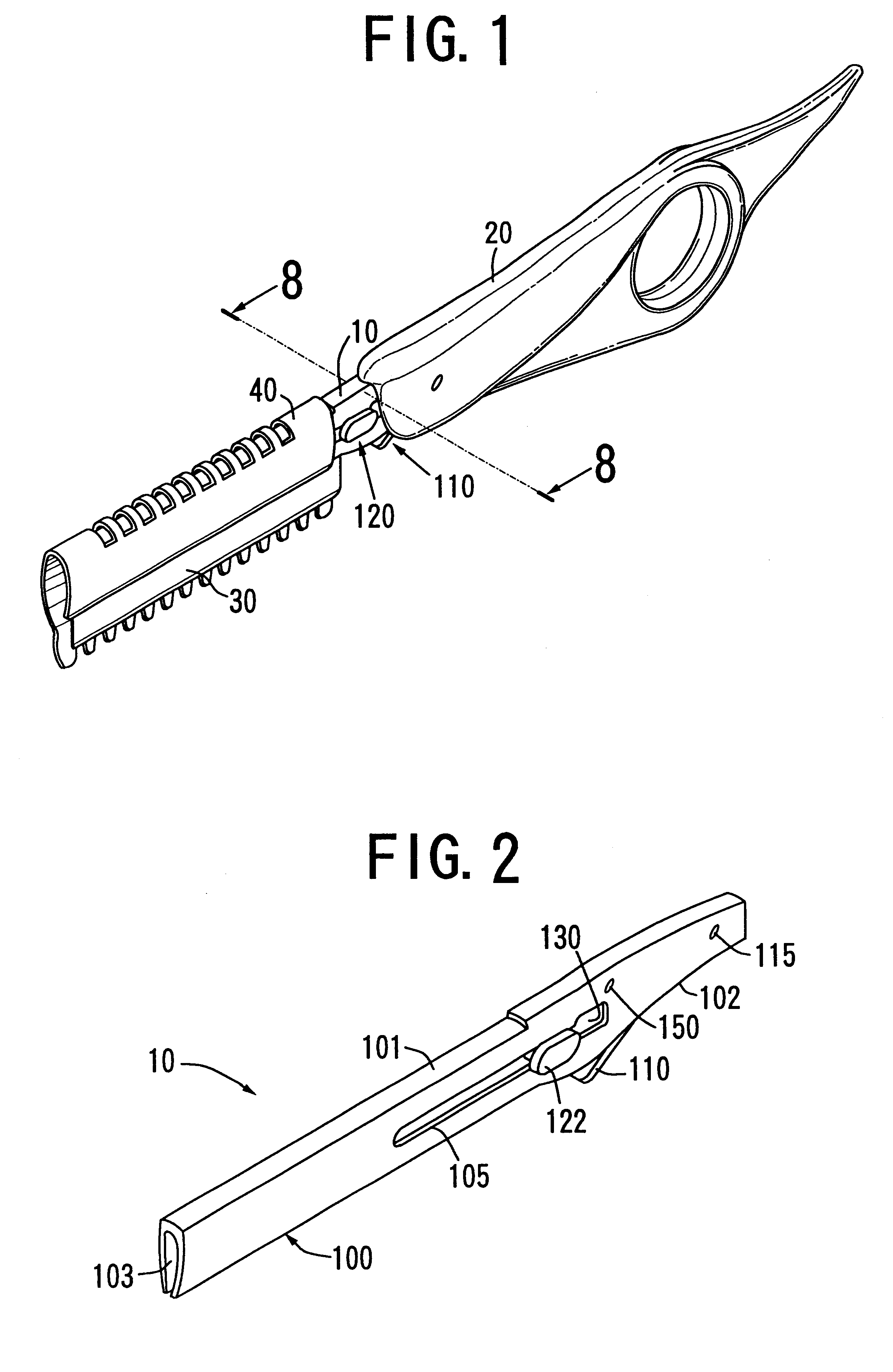
Referring to FIG. 1, the thinning razor according to the present invention includes a shank (10), a handle (20), a blade (30), a bladeguard (40), a driving member (110) and a sliding member (120).

FIG. 2 illustrates the shank (10) of the thinning razor according to the present invention. The shank (10) has a longitudinal direction which extends from a front end to an opposite rear end and has an upper surface (101) and a lower surface (102). Formed between the front end and rear end is a hollow midsection (130) being open at the lower surface (102). The front end of the shank (10) is provided with an opening (103). This opening (103) extends from the front end to the hollow midsection (130) and is open in the longitudinal direction at the lower surface (102) of the shank (10), so as to form elongated slot (100). The rear end of the shank (10) is provided with a throughhole (115).

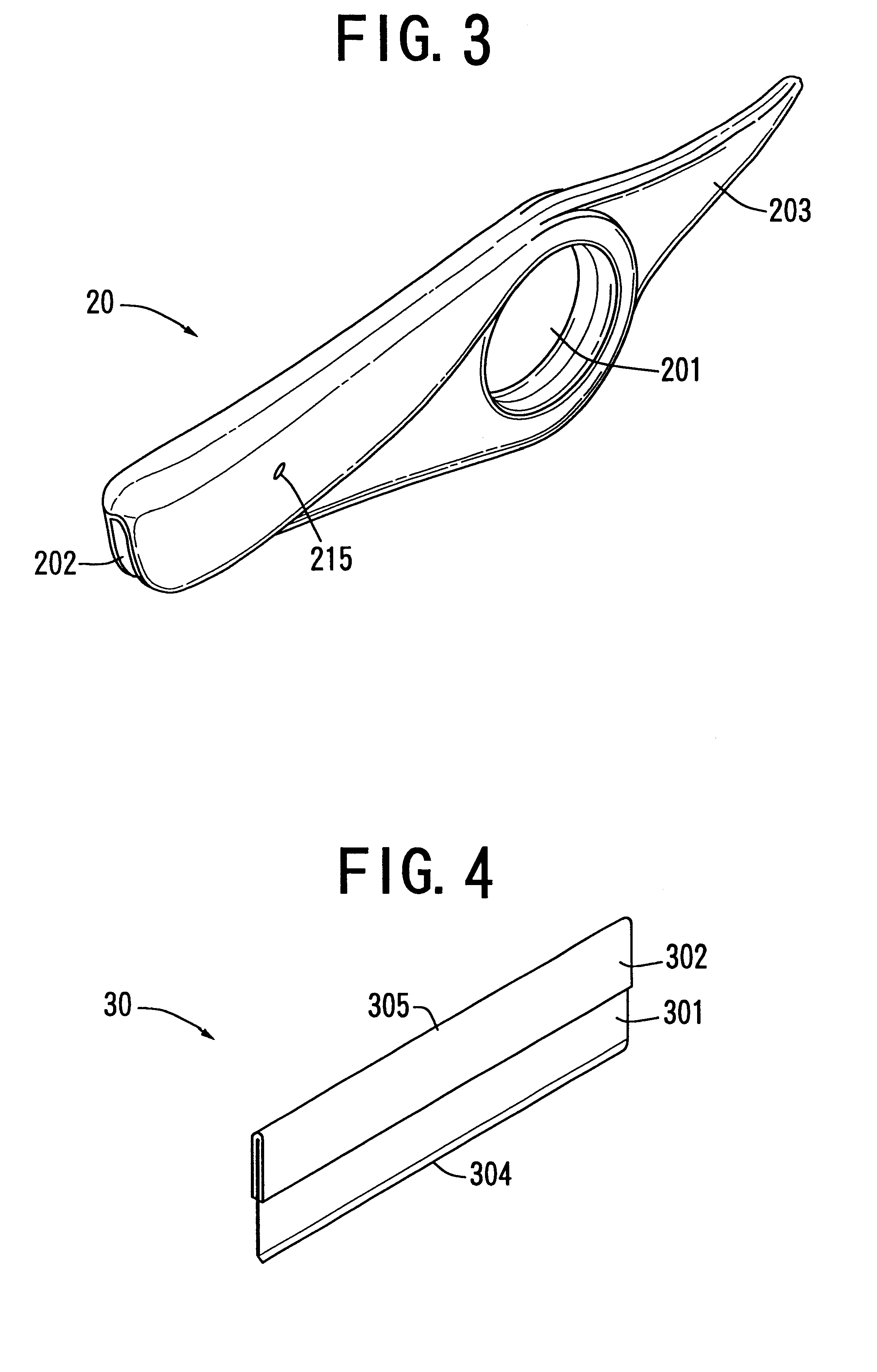
FIG. 3 illustrates the handle (20) of the thinning razor according to the present invention. The handle (2...


PUM


Abstract

A mechanical thinning razor includes a shank, a handle, a blade, a bladeguard, a driving member and a sliding member. When pushing an external surface of the driving member toward a hollow midsection of the shank, the bevel of the driving member forces the sliding member to move longitudinally over a distance that corresponds to a width of exposed segments or non-exposed segments, thereby doubling the working life of the blade.

Description

BACKGROUND OF THE INVENTION1. Field of the InventionThe present invention relates to a thinning razor, and more specifically it relates to a purely mechanical thinning razor that includes a driving member and a sliding member.2. Discussion of BackgroundOne of the essential tools of barbers and hair stylists is a razor. Originally meant for shaving facial hair and trimming of the hairline at the back of the head, the razor has undergone substantial changes in its structure and use over the years. A typical example is a practical device called a `thinning razor` (also `hair trimming device`), which purpose basically compares to that of the traditional thinning shears, namely to thin out strands of hair so that a less voluminous look can be created. Contrary to the thinning shears, the thinning razor achieves a smooth and elegant appearance of the hair, the reason being that separated strands of hair are shaved in a downward direction over an angle that conforms with the natural flow o...

Claims


Application Information

Patent Timeline
Patent Type & Authority Patents(United States)
IPC IPC(8): B26B21/12B26B21/08B26B21/40
CPCB26B21/12
Inventor HIRANO, TORU
Owner TOKYO RIKI
Why Eureka
Try Eureka