Centrifugal braking device for double bearing reel

a centrifugal braking and reel technology, applied in the direction of reels, braking systems, animal husbandry, etc., can solve the problems of large braking force, difficult adjustment of braking force, and significant increase in generated braking for

Inactive Publication Date: 2001-07-03
SHIMANO INC
View PDF9 Cites 26 Cited by
  • Summary
  • Abstract
  • Description
  • Claims
  • Application Information

AI Technical Summary

Benefits of technology

According to the present invention, the adjustment of the braking force may be easily carried out since the number of the pivoting brake members which are able to make contact with the braking liner is readily varied by operating the moving mechanism. Also, a large braking force is obtained since the pivoting brake members are moved outwardly in the radial direction by the centrifugal forces. Moreover, a distinctive difference in the braking force may be obtained by an adjustment since the braking force is adjusted stepwise by changing the number of the contacting portions which make contact with the braking liner.Various details of the invention may be changed without departing from its spirit nor its scope. Furthermore, the foregoing description of the embodiments according to the present invention is provided for the purpose of illustration only, and not for the purpose of limiting the invention as defined by the appended claims and their equivalents.

Problems solved by technology

However, the generated braking force becomes significantly large when the spool is rotated at high speed as, for instance, during casting out of the fishing line.
Accordingly, it is difficult to adjust the braking force.
Although the adjustment of the braking force may be easily carried out by rotating the dial in the above conventional centrifugal braking device, a large braking force is hardly obtained since the braking force which is exerted upon making contact with the brake shoe is obtained by the force of the movement of the brake members outwardly in the axial direction.
That is, since the brake members move outwardly in the axial direction, not outwardly in the radial direction, it is difficult to efficiently obtain a centrifugal force which acts in the radial direction as a braking force.

Method used


Image

  • Centrifugal braking device for double bearing reel
  • Centrifugal braking device for double bearing reel
  • Centrifugal braking device for double bearing reel

Examples


Embodiment Construction

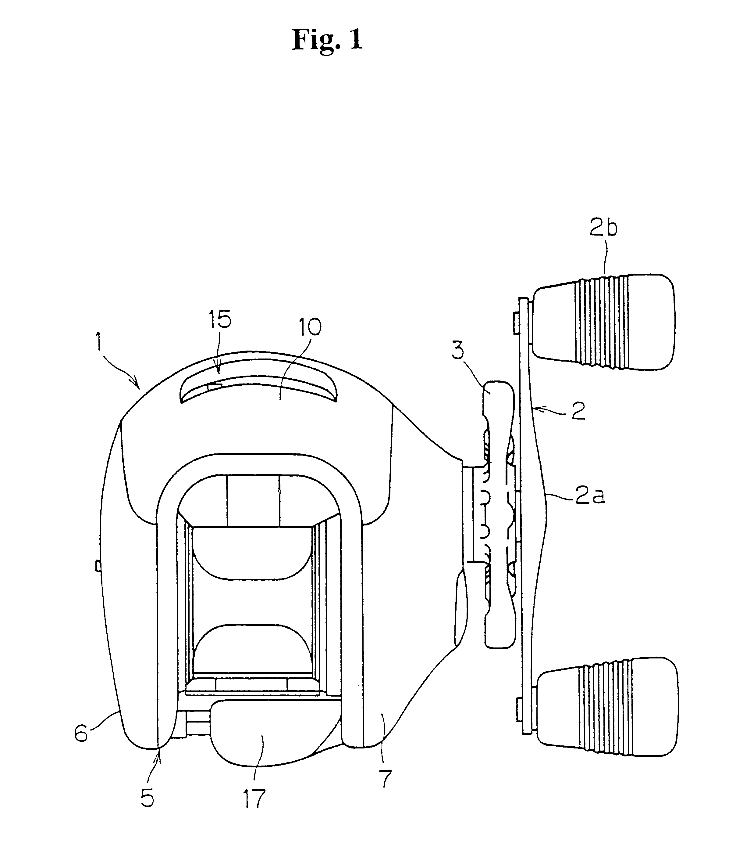
FIG. 1 is a plan view of a double bearing reel in accordance with one embodiment of the present invention.

The double bearing reel shown in the FIG. 1 is a bait reel mainly used for a lure fishing and includes a reel body 1, a handle 2, and a star drag 3. The handle 2 is provided for rotating a spool and is disposed at one side of the reel body 1. The star drag 3 is disposed between the handle 2 and the adjacent side of the reel body 1. The handle 2 is of a double handle type which includes an arm portion 2a and holding portions 2b, each of which is rotatably provided with respective end of the arm portion 2a. The outer surface of the arm portion 2a of the handle 2 is a smooth jointless surface so that a fishing line is not likely to become entwined around the arm portion 2a.

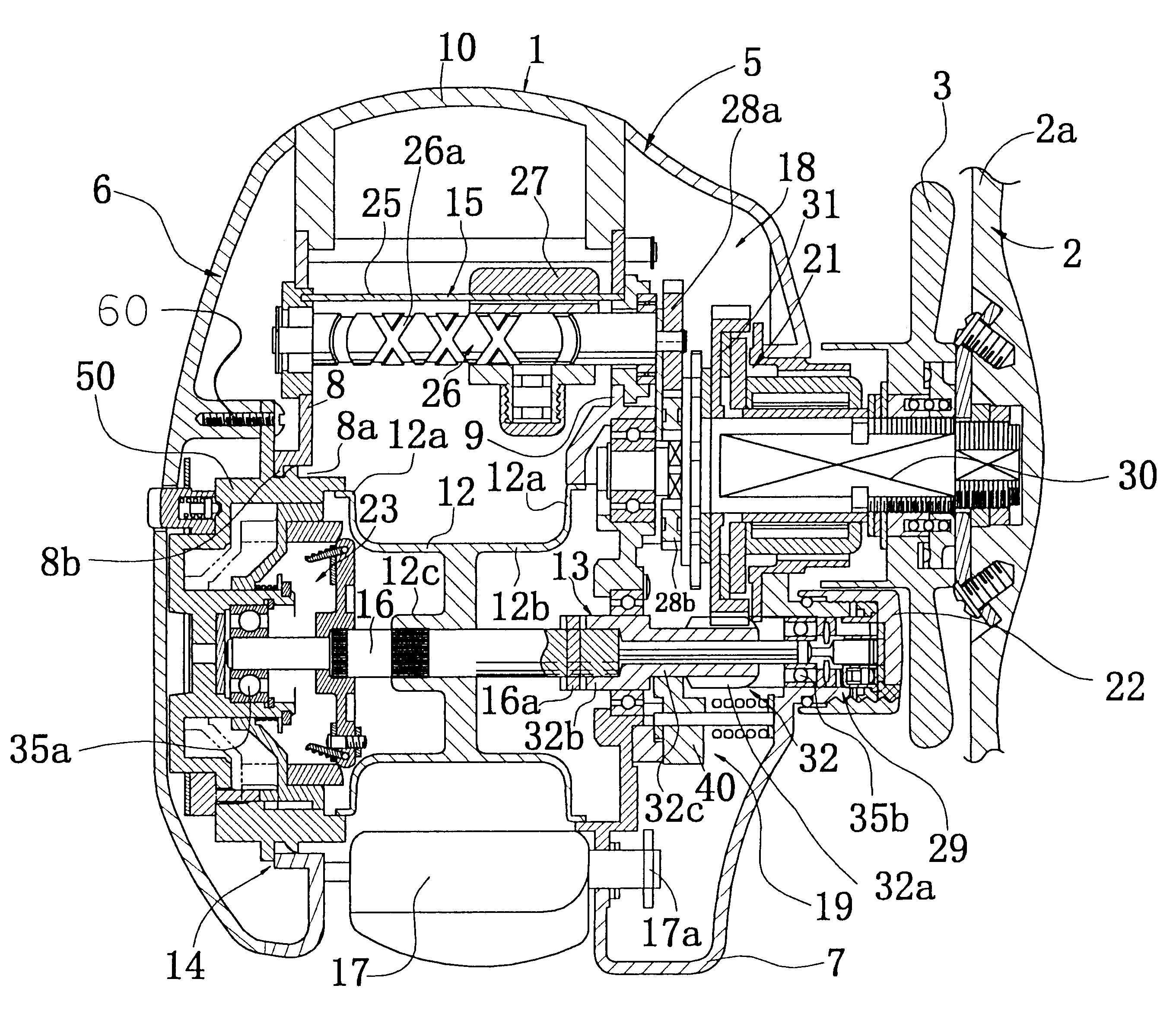
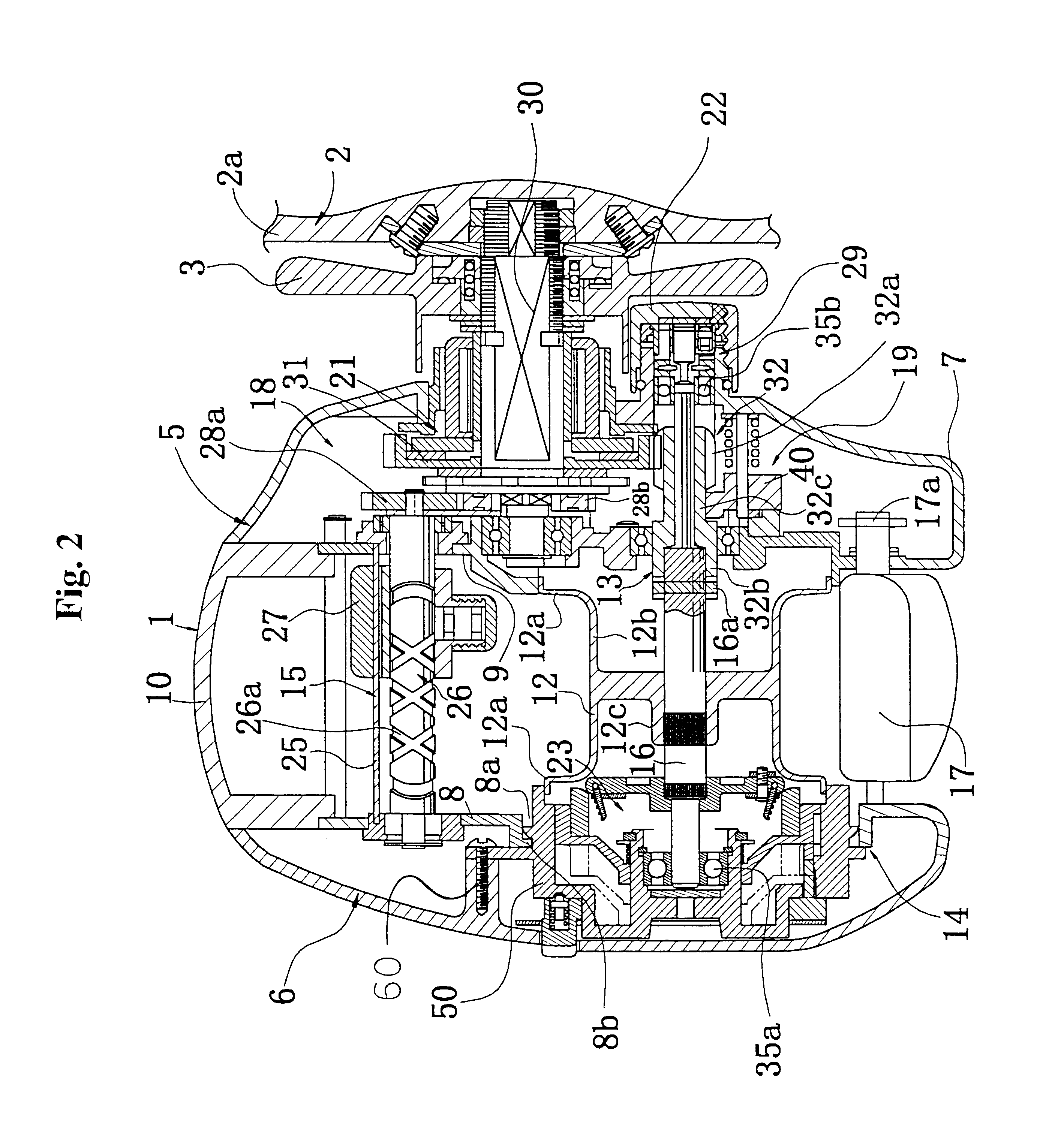
As shown in FIG. 2, the reel body 1 includes a frame 5, a first side cover 6, a second side cover 7, and a front cover 10. The first side cover 6 and the second side cover 7 are provided on respective opposite si...


PUM


Abstract

A centrifugal braking mechanism is a device for braking a spool that is rotatably supported in a reel body. The braking mechanism uses centrifugal forces in order to produce braking force against rotation of the spool. The braking mechanism includes a plurality of brake members, a brake housing having a cylindrically shaped brake liner, and an adjusting mechanism. Each of the plurality of brake members is configured to move in a radially outward direction relative to the spool in response to rotation of the spool. The brake housing and brake liner are moveable in an axial direction relative to the spool and brake members such that any selected number of the brake members may contact the brake liner to generate the braking force. The adjusting mechanism is used to selectively move the brake housing and brake liner into any of a plurality of axial positions thereby determining the number of brake members that are contactable with the brake liner in response to centrifugal force. The level of braking force desired is determined by the number of brake members that may contact the brake liner.

Description

1. Field of the InventionThe present invention relates to a centrifugal braking device. More specifically, the present invention relates to a centrifugal braking device for double bearing reel that is configured for providing braking force to a spool that is rotatably supported in a reel body of a double bearing reel, the centrifugal braking device working in response to centrifugal forces.2. Background InformationA double bearing reel is mainly used for lure fishing and is also referred to as a bait reel. In such a double bearing reel, braking force is typically applied to the spool in order to prevent the generation of backlash caused when the rotation speed of a spool exceeds the releasing speed of a fishing line during a casting operation. A centrifugal braking device is one braking mechanism used for reducing backlash and is capable of braking the spool using centrifugal forces generated when the spool is rotated.In general, centrifugal braking devices include a plurality of br...

Claims


Application Information

Patent Timeline
Patent Type & Authority Patents(United States)
IPC IPC(8): A01K89/0155A01K89/00
CPCA01K89/0155A01K89/01557A01K89/033A01K89/01931
Inventor MORIMOTO, SHIN'ICHIKAWASAKI, KEN'ICHI
Owner SHIMANO INC
Why Eureka
Try Eureka