
Self-blunting needle medical devices and methods of manufacture thereof

a technology of self-blunting needles and medical devices, which is applied in the direction of infusion needles, other medical devices, catheters, etc., can solve the problems of inability to precisely locate, difficulty in detecting the circular beam of light which is commensurate, and failure to accurately mate the blunting member sub-assembly with the front needle sub-assembly

Inactive Publication Date: 2001-07-03
BIO PLEXUS DELAWARE INC A CORP OF THE STATE OF DELAWARE & HAVING ITS PRINCIPAL PLACE OF BUSINESS AT +1
View PDF46 Cites 23 Cited by
  • Summary
  • Abstract
  • Description
  • Claims
  • Application Information

AI Technical Summary

Benefits of technology

Additionally, there remains a need in the art for methods and apparatus for preserving the integrity of fluid transferred through medical devices employing self-blunting needle technology by providing an improved fluid flow seal between the various components of such medical devices.

Problems solved by technology

Since alignment conditions are never perfect, it is difficult to detect the circular beam of light which is commensurate with precise alignment, i.e., variations within the components allow the front needle cannula to be slightly tilted within the front needle sub-assembly.
Further, while the combination of the optical system and inserter can locate the back of the front needle cannula very accurately and then move the inserter to a position commensurate with the location, it does not precisely locate the blunting member which, of course, must enter the back of the front needle cannula for successful insertion.
Thus, slight variations in the blunting member sub-assembly itself or misalignment in the clamping of the blunting member sub-assembly by the inserter can cause a failure to accurately mate the blunting member sub-assembly with the front needle sub-assembly.
In summary, the step of insertion of the blunting member cannula into the back of the front needle cannula is inefficient and time-consuming.
Leakage of air through the space inherently existing between the blunting member outer diameter and the front needle inner diameter, such air thereafter flowing through the blunting member cannula into the collection tube, will cause undesirable foaming in the collection tube.

Method used


Image

  • Self-blunting needle medical devices and methods of manufacture thereof
  • Self-blunting needle medical devices and methods of manufacture thereof
  • Self-blunting needle medical devices and methods of manufacture thereof

Examples


Embodiment Construction

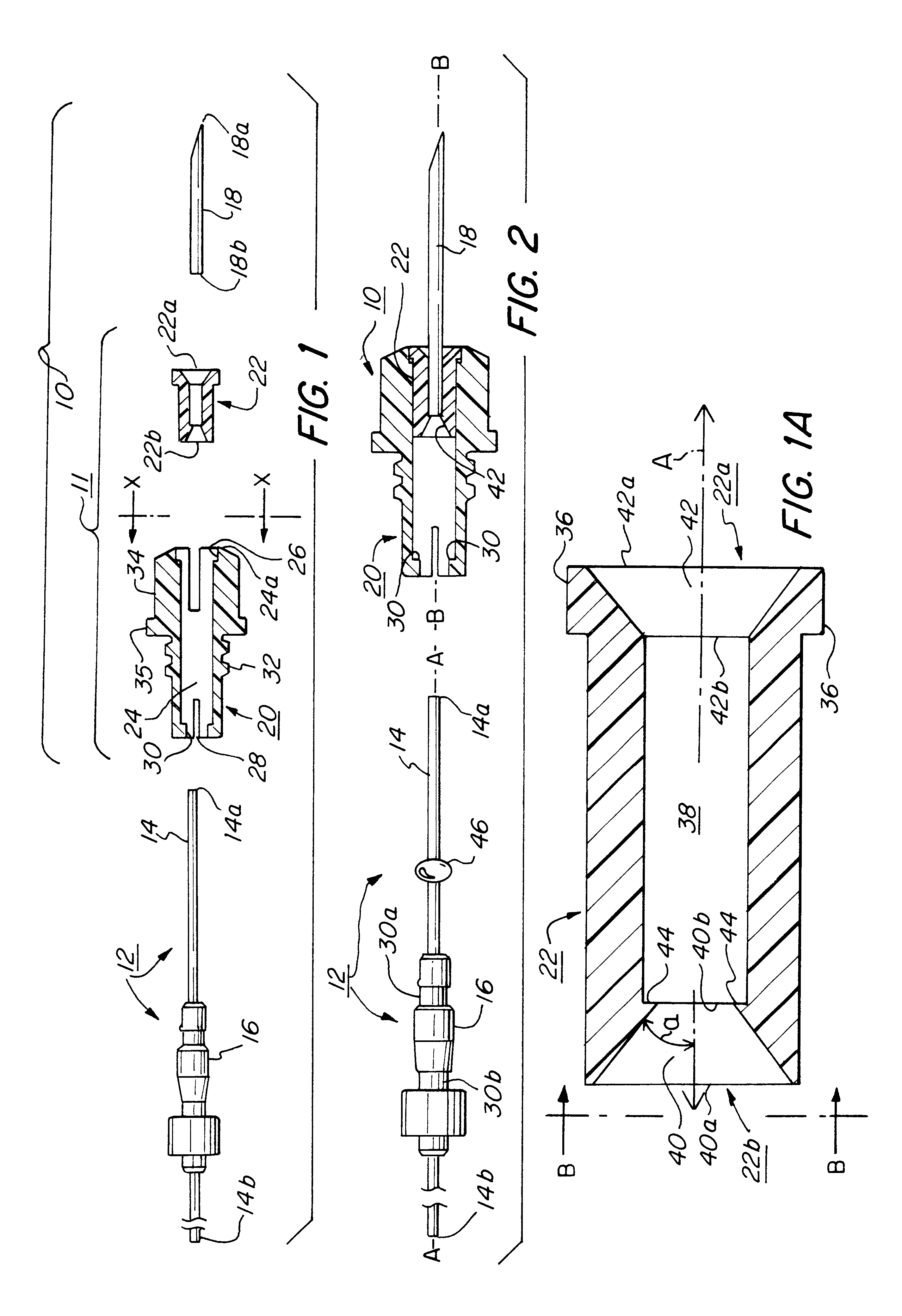
The present invention relates to self-blunting needle assemblies of the type that comprise a needle cannula and a blunting member disposed telescopically one within the other, one comprising an external component having a through-bore there-through and the other comprising an internal component that is received within the through-bore. The blunting member may be disposed within the needle cannula or, in alternative embodiments, the blunting member may be hollow and the needle cannula may be disposed within the blunting member. In either case, the blunting member and the needle cannula are movable relative to each other between a sharpened configuration and a blunted configuration, i.e., from the sharpened configuration to the blunted configuration or from the blunted configuration to the sharpened configuration and, optionally, back again. In the sharpened configuration (optionally also referred to as the "insertion configuration"), the puncture tip of the needle cannula extends bey...


PUM


Abstract

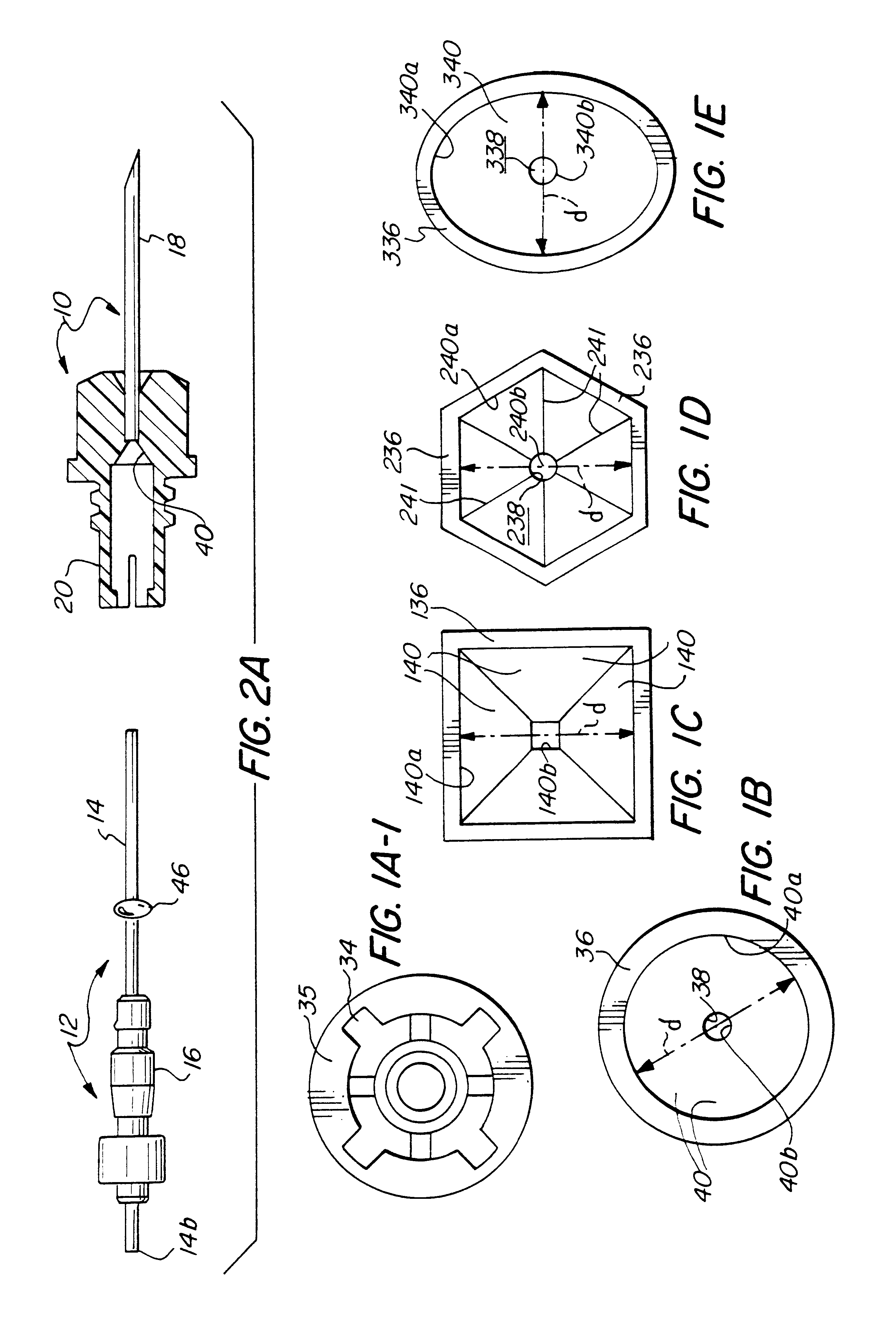
A self-blunting needle medical device comprises a needle cannula (18) fixed to a hub (20) having a receiving structure therein such as ferrule (22) and a movable blunting member (14) movably received within the cannula (18). Ferrule (22) defines a passage (38) extending therethrough, within which both the cannula (18) and the movable member (14) can be received and which establishes a coaxial relationship between them. The ferrule (22) defines a first guide surface (40) for directing the blunting end (14a) of the movable member (14) into the central bore of the cannula (18) during assembly. A second guide surface (42) performs the function of guiding the mounting end (18b) of the cannula (18) into ferrule (22) for mounting therein. Typically, the cannula (18) has a tissue puncture tip (18a). When the movable member (14) is retracted into the cannula (18), the puncture tip (18a) is exposed for use, e.g., injection into tissue. The movable member (14) is then moved to an extended position in which blunting end (14a) projects beyond the puncture tip (18a), to render the device safe with regard to subsequent accidental needle sticks. Methods of assembling the self-blunting needle are also presented. In various embodiments, the guide member may be integral with the assembled device or may be defined by a guide member that is used only in the assembly process and from which the assembled device may be removed.

Description

1. Field of the InventionThe present invention relates to medical devices comprising self-blunting needles and to methods of manufacture of such self-blunting needle medical devices. More specifically, this invention is directed to improved medical devices of the type including a needle and blunting member which are movable relative to each other and to a method of manufacture thereof.2. Related ArtFor reasons which have received wide publicity, there is substantial demand for venipuncture products which may be employed by healthcare workers with minimal risk of incurring an accidental needle-stick wound. A highly successful product of this nature is a self-blunting needle assembly sold under the registered trademark "PUNCTUR-GUARD" by Bio-Plexus, Inc. of Vernon, Conn. The "PUNCTUR-GUARD" needle assembly is manufactured in accordance with the teachings of U.S. Pat. No. 4,828,547, entitled "Self-Blunting Needle Assembly and Device Including the Same", issued on May 9, 1989 to Carl R....

Claims


Application Information

Patent Timeline
IPC IPC(8): A61M25/06A61M5/32A61M5/158
CPCA61M25/0643A61M5/3243A61M2005/3212
Inventor BURZYNSKI, MARK J.JONES, ALEXANDER K.KEARNS, RICHARD S.POLIDORO, JOHN M.SAHI, CARL R.SMUTNEY, CHAD C.
Owner BIO PLEXUS DELAWARE INC A CORP OF THE STATE OF DELAWARE & HAVING ITS PRINCIPAL PLACE OF BUSINESS AT
Learn More