3D tessellation imaging

a 3d tessellation and imaging technology, applied in the field of 3d tessellation imaging, can solve the problems of posing a formidable challenge to mapping neuronal interconnections in brain tissue volumes, unsatisfactory as a high-resolution volume mapping solution, and great difficulties, and achieves the effect of removing the time-consuming step of transforming sim, reducing the difficulty of transforming sim, and high imaging speed

Inactive Publication Date: 2016-12-22
MERMELSTEIN MICHAEL +1
View PDF3 Cites 0 Cited by
  • Summary
  • Abstract
  • Description
  • Claims
  • Application Information

AI Technical Summary

Benefits of technology

[0014]For applications like brain tissue imaging, a higher imaging speed, with a freedom from artifacts, and with isotropic resolution is desirable.
[0015]The present invention seeks to improve on prior art structured illumination microscopy for high-speed volume scanning of transparent tissue specimens by (1) removing the time-consuming step of transforming SIM patterns between frames, (2) providing a simple image interpretation with a reduced likelihood of undesirable image artifacts, and (3) providing isotropic resolution in transparent specimen volumes. The new method, 3D Tessellation Imaging (3DTI), comprises an interference-pattern structured illumination microscope with a number of illumination beams. The hallmarks of 3DTI include the nature of the projected pattern and the interpretation of imagery sensed during specimen translation through this pattern. Specifically, a region of the specimen volume is filled with a sparse, regular pattern of brightly-peaked kernels that form a tessellation of three-space. Those bright peaks are surrounded by a buffer of relative darkness. The 3D pattern divides a collection PSF overlaid in the same space. A substantially transparent specimen is translated through the field of bright peaks and a conventional fluorescenc...

Problems solved by technology

This poses a formidable challenge to mapping neuronal interconnections in brain tissue volumes.
Although light microscopy is a well-established and powerful modality for investigating biological systems, it is as yet not ideal as a high-resolution volume mapping solution.
And yet, great difficulties remain.
Super-resolution techniques remain slow, or are often limited by optical or mechanical complexity, or are not compatible with large three-dimensional samples, or are not compatible with a wide range of wavelengths, or have limited fields of view, or have anisotropic resolution in three dimensions.
In low light, as in fluorescence im...

Method used


Image

  • 3D tessellation imaging
  • 3D tessellation imaging
  • 3D tessellation imaging

Examples


Embodiment Construction

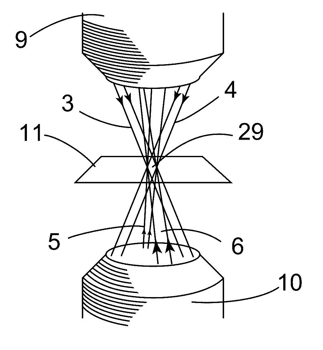
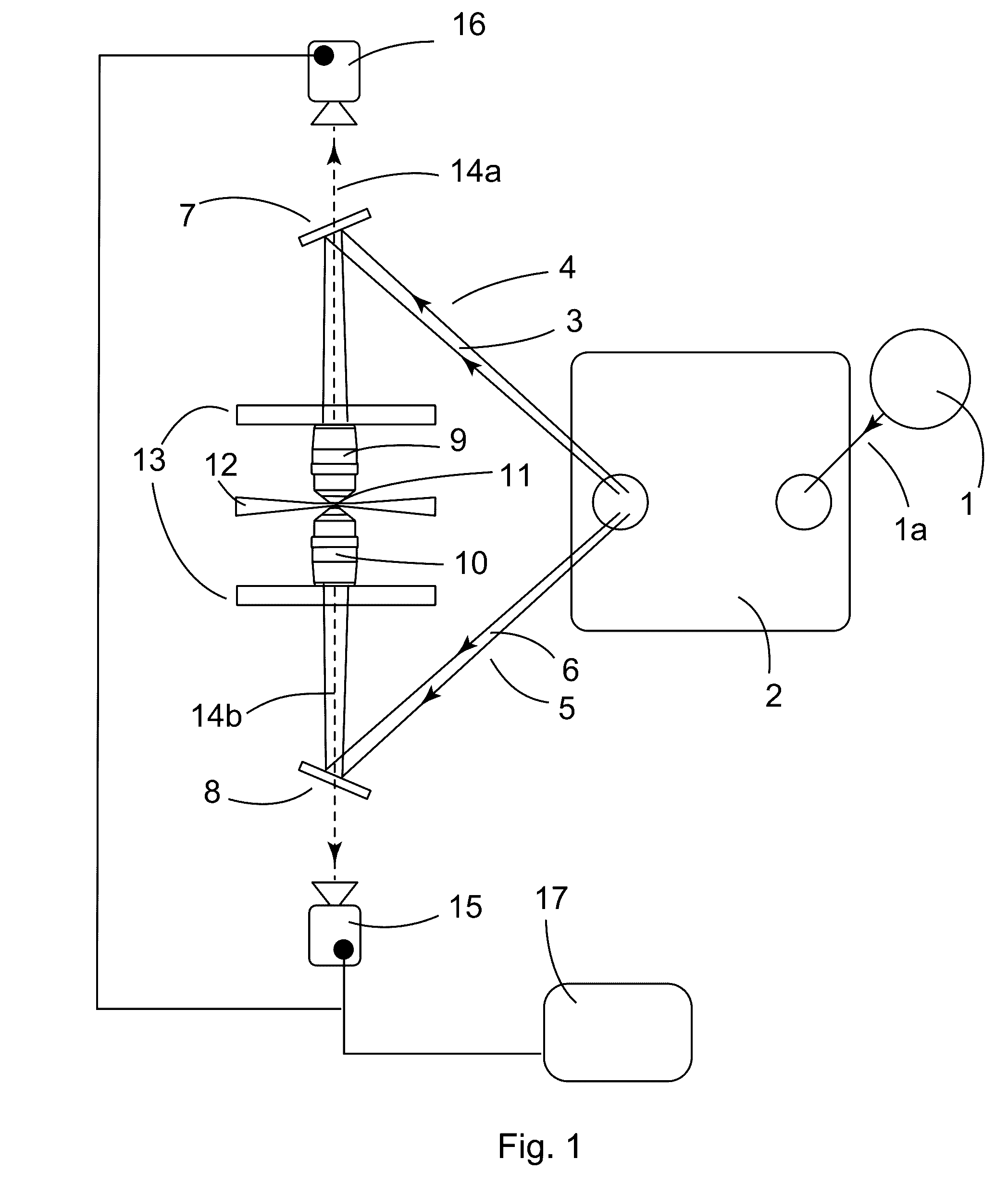
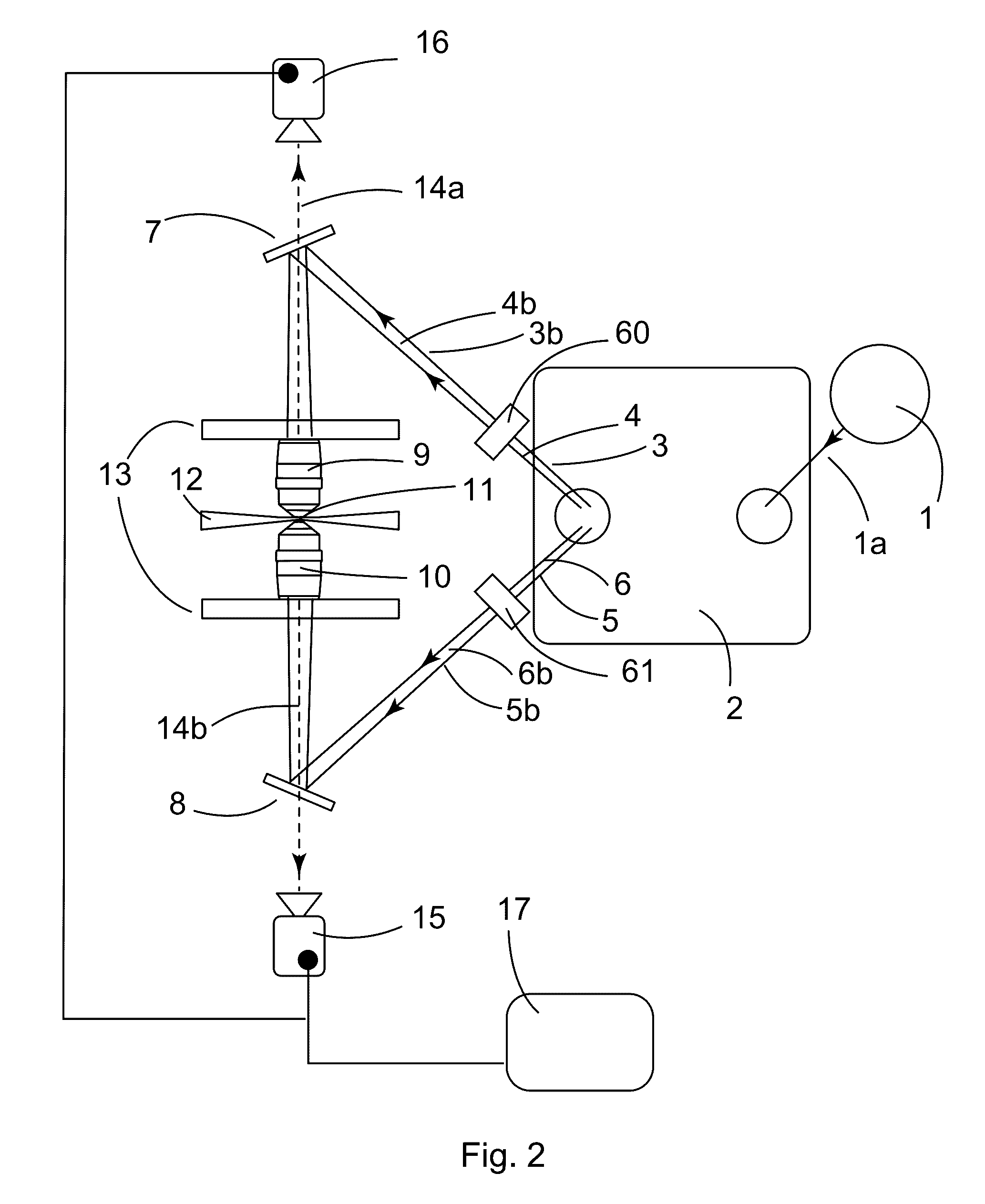
[0028]A schematic representation of a 3D Tessellation Imaging (3DTI) setup is shown in FIG. 1. In a preferred embodiment, a single coherent input beam 1a from a light source 1 is split into several output beams 3, 4, 5, and 6 by beam conditioning optics 2. For example, the beam conditioning optics can be an assembly of beamsplitters, mirrors, and lenses that control the phase, beam direction, and beam focus in a manner well known to the art. In this embodiment, these output beams are then directed through an optical system comprised of steering mirrors 7 and 8 which aim the output beams into the rear aperture of two objective lenses 9 and 10 suitably mounted on a rigid and stable platform 13. The objective lenses recombine the beams in a predetermined region of overlap (see FIG. 3 for example) where a specimen 11 is positioned on a translating stage 12. The overlapping beams form a crystalline interference pattern (a 3D tessellation) used to illuminate selected portions of the speci...


PUM


Abstract

The invention provides a new system and method for imaging a specimen. The system projects a three-dimensional crystalline pattern of light, a tessellation, and records the specimen's emitted light at locations where a portion of the specimen coincides with the pattern.

Description

CROSS-REFERENCE TO RELATED APPLICATIONS[0001]This application claims the benefit of provisional patent application No. 62 / 182,096, filed Jun. 19, 2015.STATEMENT REGARDING FEDERALLY SPONSORED RESEARCH OR DEVELOPMENT[0002]Not applicableTHE NAMES OF THE PARTIES TO A JOINT RESEARCH AGREEMENT[0003]Not applicableSEQUENCE LISTING OR PROGRAM[0004]Not applicableSTATEMENT REGARDING PRIOR DISCLOSURES BY THE INVENTOR OR A JOINT INVENTOR[0005]Not applicableBACKGROUND OF THE INVENTION[0006]Field of Invention[0007]The invention relates to the projection of a pattern of radiation and particularly to a system and method using a projected radiation pattern to improve fluorescence imaging.[0008]Summary of Prior Art[0009]Biology is intricately organized at the nanoscale, yet its functional elements, such as the neuronal networks in the brain, often span over distances of centimeters. This poses a formidable challenge to mapping neuronal interconnections in brain tissue volumes.[0010]Although light micr...

Claims


Application Information

Patent Timeline
IPC IPC(8): G01N21/64G02B21/00
CPCG01N21/6458G02B21/0032G01N2021/6471G02B21/0076G02B21/0028G01N2021/6463G02B21/0056G02B21/367
Inventor MERMELSTEIN, MICHAELABNET, CHARLES CAMERON
Owner MERMELSTEIN MICHAEL
Why Eureka
Try Eureka