
Retrofit Computer Cooler

Inactive Publication Date: 2001-07-03
GALIS OSCAR
View PDF3 Cites 18 Cited by
  • Summary
  • Abstract
  • Description
  • Claims
  • Application Information

AI Technical Summary

Benefits of technology

A first primary object of the principles relating to the present invention is a retrofit cooling system for the provision of a PC which effectively lowers the operating temperature of the CPU.
A second auxiliary objective of the third primary object of the principles relating to the present invention is the provision of a retrofit cooling system for a PC which effectively lowers the ambient temperature inside a PC enclosure.

Problems solved by technology

Most importantly, perhaps, a retrofit blower fitting in the space reserved for an additional disk drive denies the use of that space for the installation of an additional disk drive.
For this reason these devices are considered undesirable.
These constructions are characterized by air flow throughout the enclosure and are considered to provide a less than satisfactory cooling as a result.
These are considered major impediments to implementation.
Lastly, there is no specific provision for cooling of the CPU which is not among the components readily contained by a rearrangement of components for disposition within this secondary interior enclosure.

Method used


Image

  • Retrofit Computer Cooler
  • Retrofit Computer Cooler
  • Retrofit Computer Cooler

Examples


Embodiment Construction

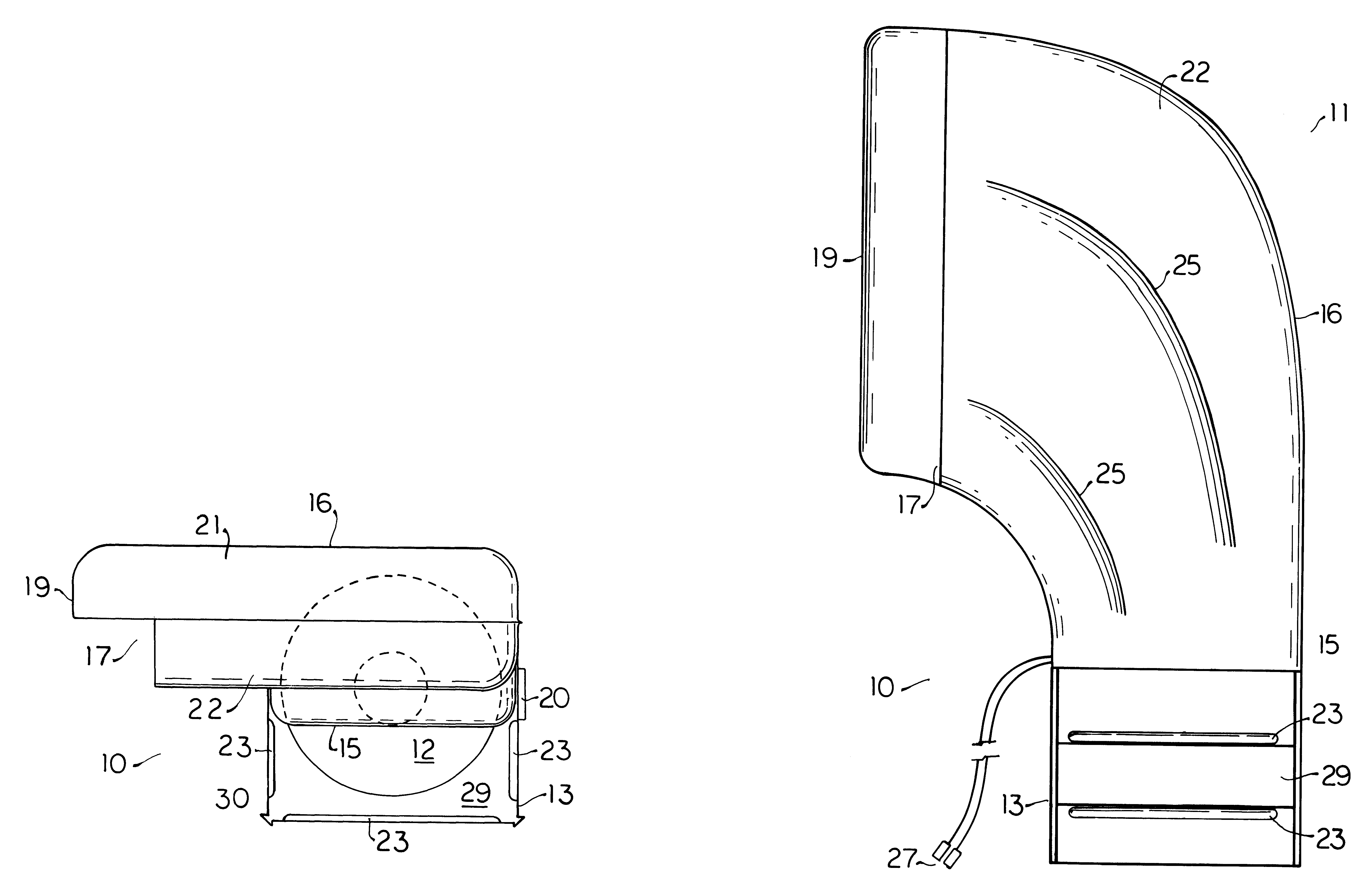
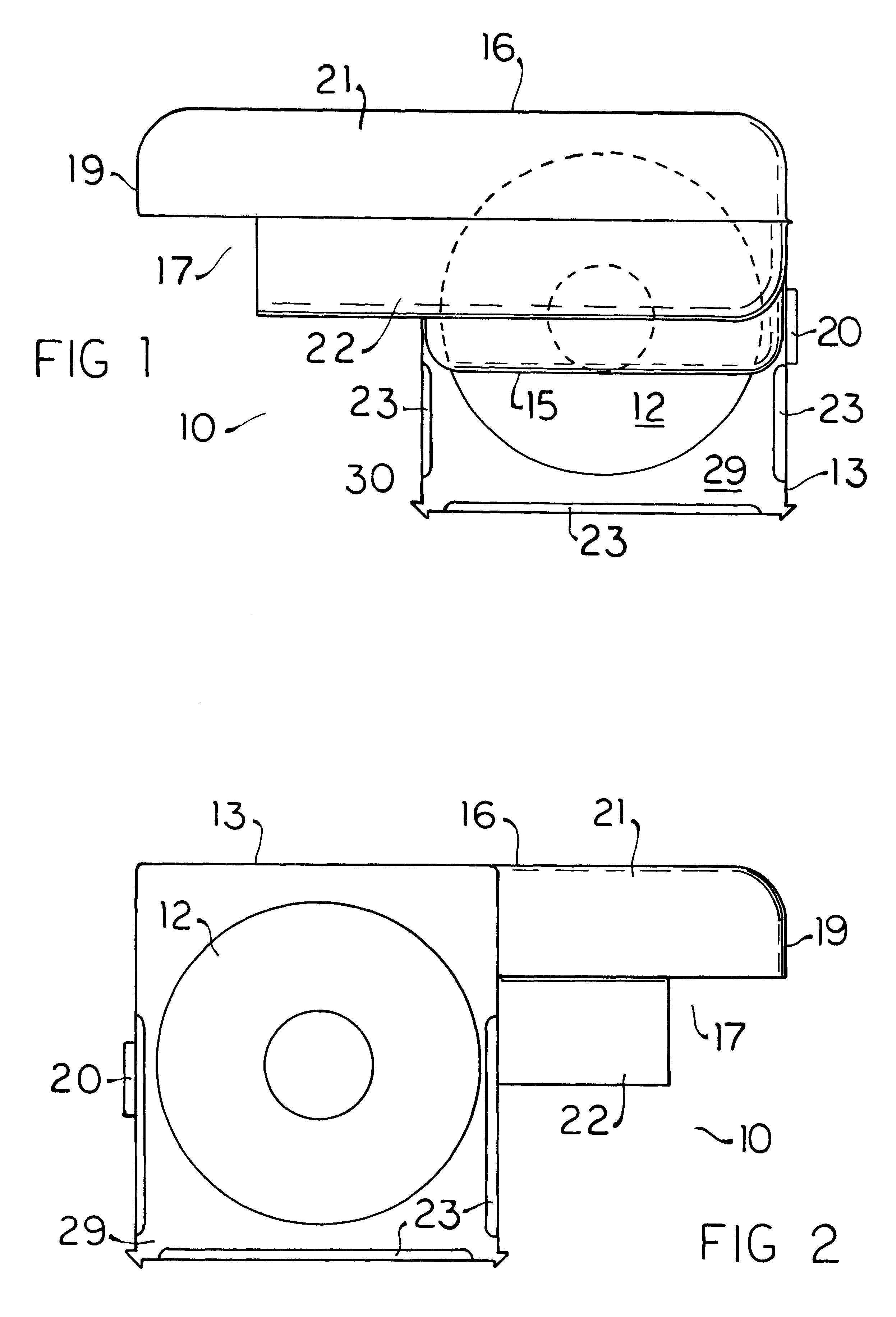
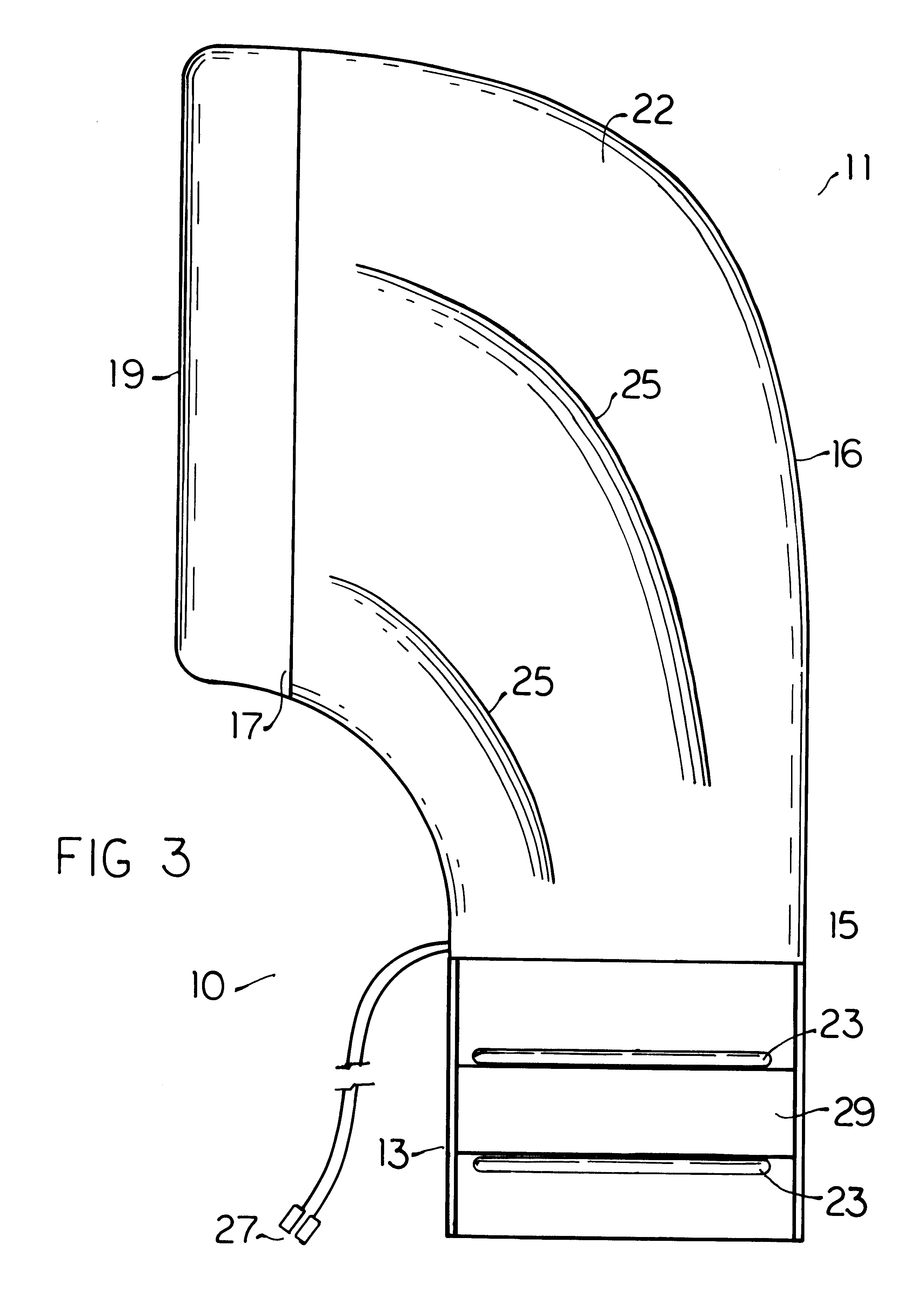
A PC cooler 10 comprising a preferred embodiment of the principles relating to the present invention is depicted in FIGS. 1-4 which is seen therein to consist of an arcuate duct 11, a blower 12 and a blower housing 13 disposing an arcuate duct inlet 15 adjacent to the downwind face 30 of an upper portion of the blower 12. As depicted it is preferred that this upper portion of the blower 12 disposed adjacent to the arcuate duct inlet 15 encompass approximately three quarters, i.e. about 75%, of the face of the blower 12 with the lower quarter left open to force air straight ahead.

Correctly installed in a PC with the blower disposed against the opening in the rear wall of the PC created by removing a removable panel in the rear wall this lower portion of the blower 12 is disposed directly behind the integrated circuit (IC) cards which are disposed in an upright parallel spaced apart relation to each other. In front of these cards which typically provide such functions as a modem, grap...


PUM


Abstract

An arcuate duct has an inlet continuous with a housing about a blower and an outlet perpendicular to the blower which further has a lip directing the air flow perpendicularly. The arcuate duct transforms an air flow intake along an X axis smoothly to air flow parallel a Y axis and the outlet lip directs the air flow parallel a Z axis given a horizontal disposition of the arcuate duct main body which utilized in a desktop PC. A vertical disposition is utilized in a tower type PC. In either case the blower is disposed adjacent an opening in the rear of the PC enclosure created by removing a removable panel and the arcuate main duct body is positioned between the IC cards and HDD on one side and the PC enclosure on the other side, being slightly compressed between the two to maintain positioning. Air flow through the arcuate duct is directed against the CPU and RAM. The lower portion of the blower is left open to blow air directly ahead past the IC cards against the HDD and auxiliary disk drives in front. The arcuate duct outlet is larger than the inlet minimizing back pressure and promoting laminar flow therethrough while an abrupt change of direction caused by the lip of the outlet induces turbulent flow and increased convection. Installation requires no rearrangement of components in the PC and no fixed attachment to the PC.

Description

1. Field of the InventionThe present invention relates generally to electrical systems and devices with cooling means, more particularly to electrical systems and devices using air for cooling, and most specifically to electrical systems and devices using a fan or blower for cooling.2. General BackgroundThe current widespread use of computers in the home is considered to have originated with the advent of the IBM (International Business Machines) PC (Personal Computer) in the early 1980s. Subsequent to this introduction diverse companies manufactured and sold what are commonly known as IBM Compatible PCs which are characterized by use of a DOS (Disk Operating System), particularly MS (MicroSoft) DOS and Windows operating systems developed and licensed by Microsoft Corporation. The growth of this industry is considered to have been fueled by the development of faster and more powerful microprocessors such as those developed in the early 1990s by Intel Corporation and others including...

Claims


Application Information

Patent Timeline
IPC IPC(8): G06F1/20
CPCG06F1/20
Inventor GALIS, OSCAR
Owner GALIS OSCAR
Learn More