Pseudo-synchronization prevention method in SDH transmission mode, pseudo-synchronization preventing SDH transmission system, and transmitter-receiver in pseudo-synchronization preventing SDH transmission system

a transmission mode and pseudo-synchronization technology, applied in the direction of synchronisation signal speed/phase control, time-division multiplexing selection, electrical equipment, etc., can solve the problem of increasing the number of bits other than those of the information to be transmitted (main information), the possibility of pseudo-synchronization, and the effect of reducing the amount of main information

Inactive Publication Date: 2001-07-03
FUJITSU LTD
View PDF12 Cites 29 Cited by
  • Summary
  • Abstract
  • Description
  • Claims
  • Application Information

AI Technical Summary

Problems solved by technology

In such a case, a receiving side for receiving the above data may erroneously recognize a position of a header of the frame, resulting in possibility of pseudo-synchronization.
However, in the above method, it is necessary to provide a special bit as error monitoring information in addition to the synchronization pattern allocated in the frame format for the F2 byte, resulting

Method used


Image

  • Pseudo-synchronization prevention method in SDH transmission mode, pseudo-synchronization preventing SDH transmission system, and transmitter-receiver in pseudo-synchronization preventing SDH transmission system
  • Pseudo-synchronization prevention method in SDH transmission mode, pseudo-synchronization preventing SDH transmission system, and transmitter-receiver in pseudo-synchronization preventing SDH transmission system
  • Pseudo-synchronization prevention method in SDH transmission mode, pseudo-synchronization preventing SDH transmission system, and transmitter-receiver in pseudo-synchronization preventing SDH transmission system

Examples


Embodiment Construction

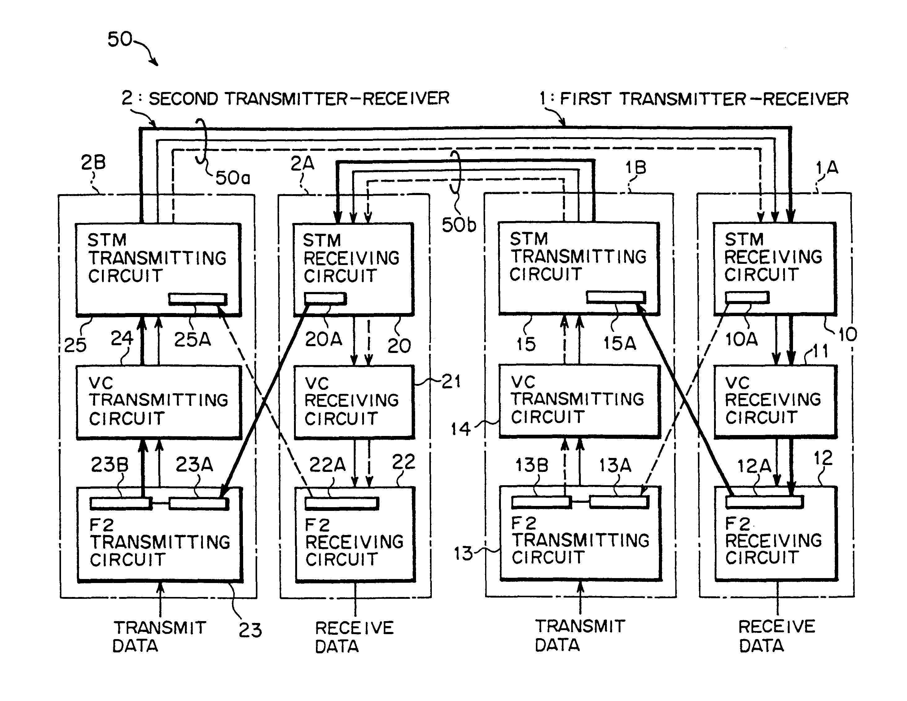
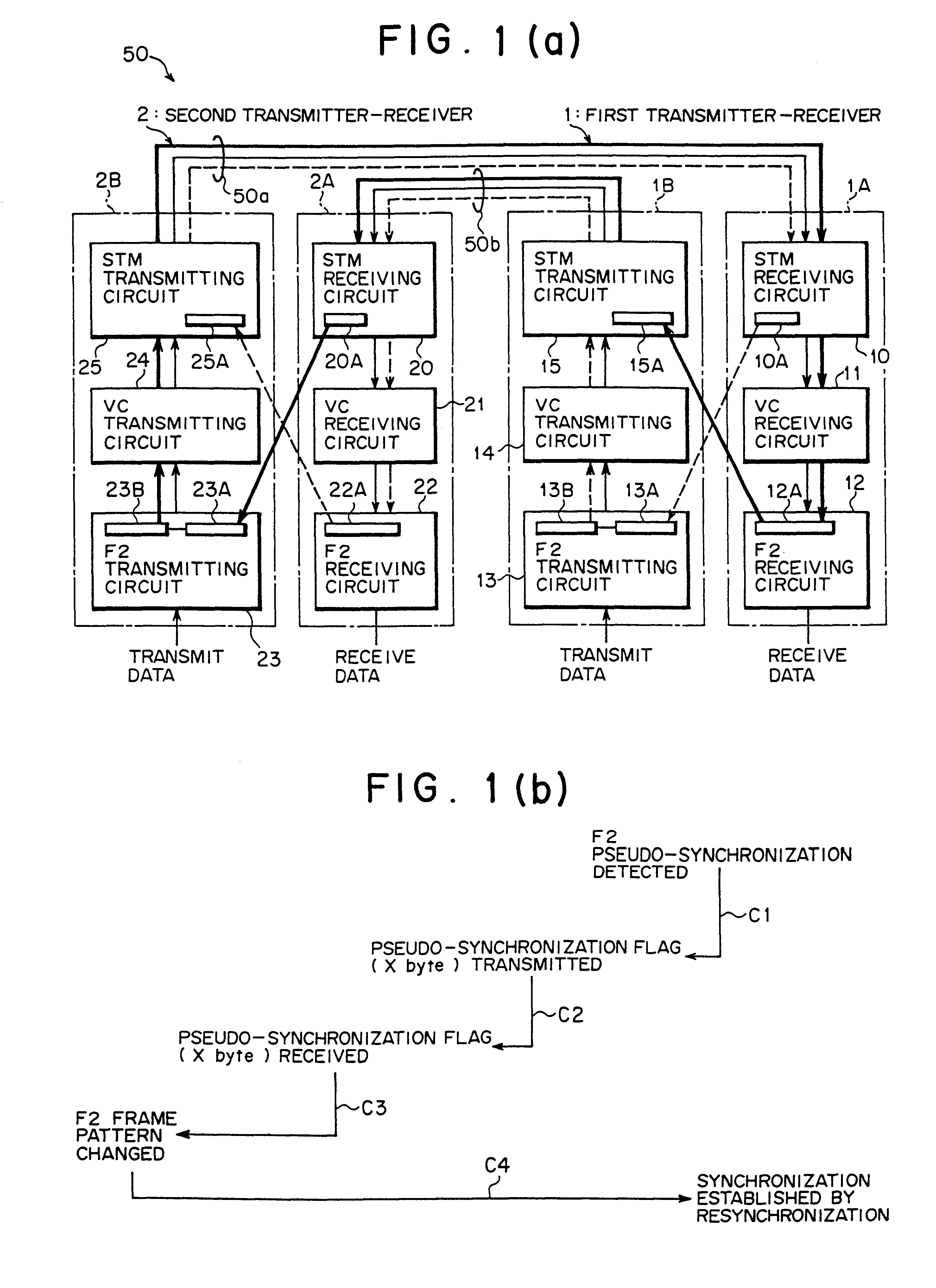
FIG. 1(a) is a block diagram showing a configuration of a pseudo-synchronization preventing SDH transmission system according to one embodiment of the present invention. A pseudo-synchronization preventing SDH transmission system 50 shown in FIG. 1(a) includes a first transmitter-receiver 1 and a second transmitter-receiver 2 which are opposed to each other. In the first transmitter-receiver 1 and the second transmitter-receiver 2, a data transmission is made according to an SDH transmission mode by using an F2 byte (predetermined byte information) in a VC path in an STM frame.

Moreover, the pseudo-synchronization preventing SDH transmission system 50 is equivalent to the optical interfaces 42, 62 (see FIG. 9) in the above-mentioned linear network 100.

Specifically, the first transmitter-receiver 1 includes a receiving unit 1A and a transmitting unit 1B. The receiving unit 1A receives data transmitted from the second transmitter-receiver 2 through an optical fiber 50a, and includes an...


PUM


Abstract

In a terminal apparatus to which an SDH transmission mode is applied, there is a method including a pseudo-synchronization detecting step of detecting, by one transmitter-receiver, that a pseudo-synchronization state is established by finding in data the same pattern as a synchronization pattern in byte information, a pseudo-synchronization posting step of inserting, by the one transmitter-receiver, information to the effect that the pseudo-synchronization state is established in an overhead of an STM frame, and posting the information to the other transmitter-receiver, and a changed synchronization pattern transmitting step of changing a synchronization pattern into an additional synchronization pattern different from the synchronization pattern in the byte information, and transmitting the synchronization pattern obtained by the change from the other transmitter-receiver to the one transmitter-receiver. Thus, it is an object of the present invention to easily prevent pseudo-synchronization by posting the message to the effect that the pseudo-synchronization state is established to an opposite terminal apparatus by using the overhead of the STM frame such that the opposite terminal apparatus can change the synchronization pattern in the byte information.

Description

(1) Field of the InventionThe present invention relates to a pseudo-synchronization prevention method in an SDH transmission mode, a pseudo-synchronization preventing SDH transmission system, and a transmitter-receiver in the pseudo-synchronization preventing SDH transmission system, all of which are suitable for use in a transmission unit to which the SDH transmission mode is applied.(2) Description of the Related ArtAccording to an SDH (Synchronous Digital Hierarchy) transmission mode defined in ITU-T, at a time of data transmission from one terminal apparatus to another terminal apparatus, data link is enabled between the terminal apparatus by using a container [minimum unit of transmission information such as F2 byte (UserCH)] in a VC (Virtual Container) path, that is, a clear channel provided to a user.In the SDH transmission mode, data to be transmitted is inserted in a predetermined frame called STM (Synchronous Transport Module) frame, and is transmitted and received with sy...

Claims


Application Information

Patent Timeline
IPC IPC(8): H04J3/06H04Q11/04H04J3/00H04L7/08
CPCH04J3/0608H04J3/0623H04J2203/0089H04J2203/005
Inventor KUDO, SHOJI
Owner FUJITSU LTD
Why Eureka
Try Eureka