
Vehicle headlamp having an outwardly and backwardly curved lens

a technology of outward and backward curved lenses and headlamps, which is applied in the direction of fixed installation, lighting and heating apparatus, lighting support devices, etc., can solve the problems of the conventional headlamp lens, the region below the reflector is liable to become a dead space, and it is impossible to effectively utilize the great power of the discharge lamp

Inactive Publication Date: 2001-07-10
KOITO MFG CO LTD
View PDF11 Cites 2 Cited by
  • Summary
  • Abstract
  • Description
  • Claims
  • Application Information

AI Technical Summary

Benefits of technology

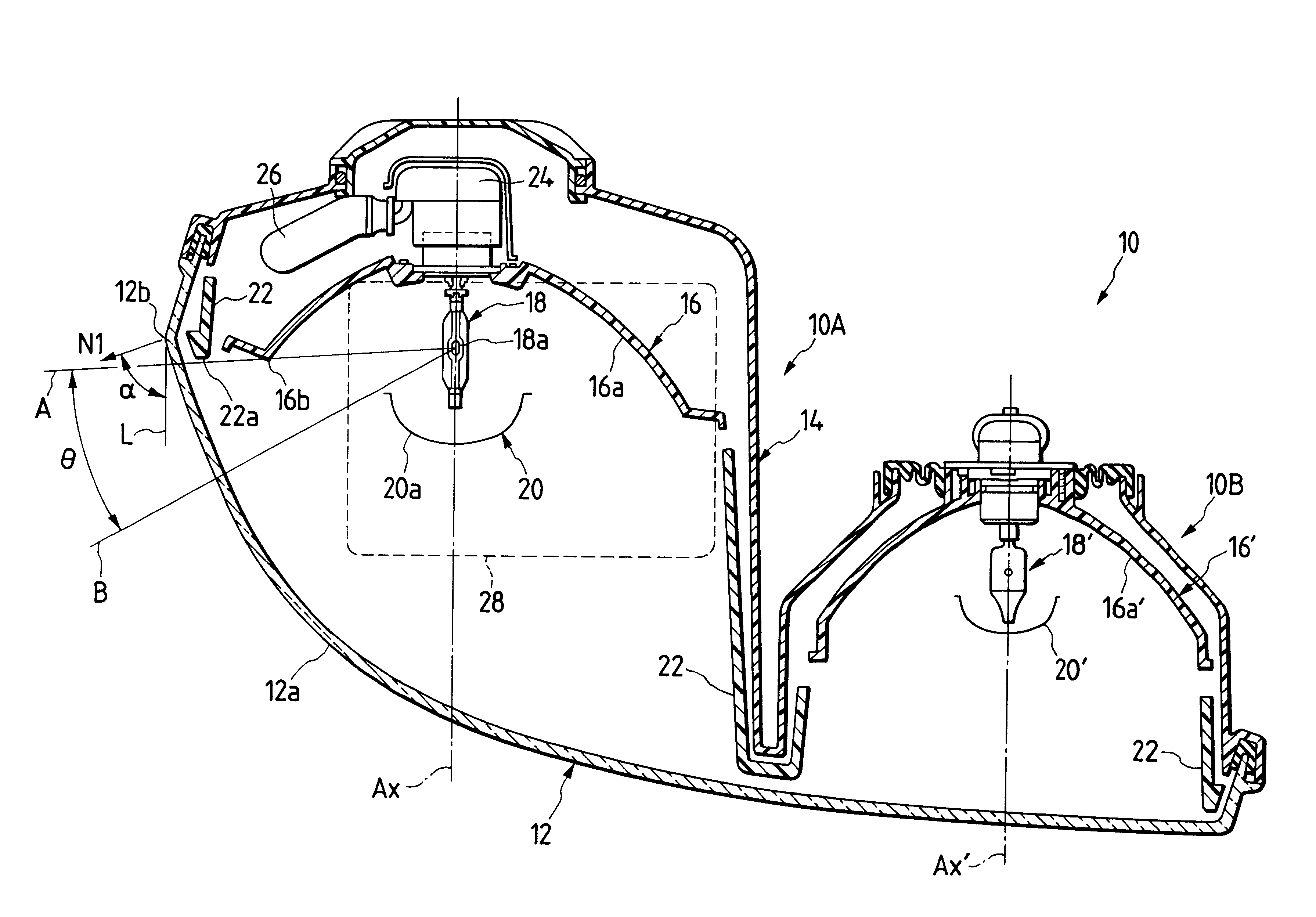
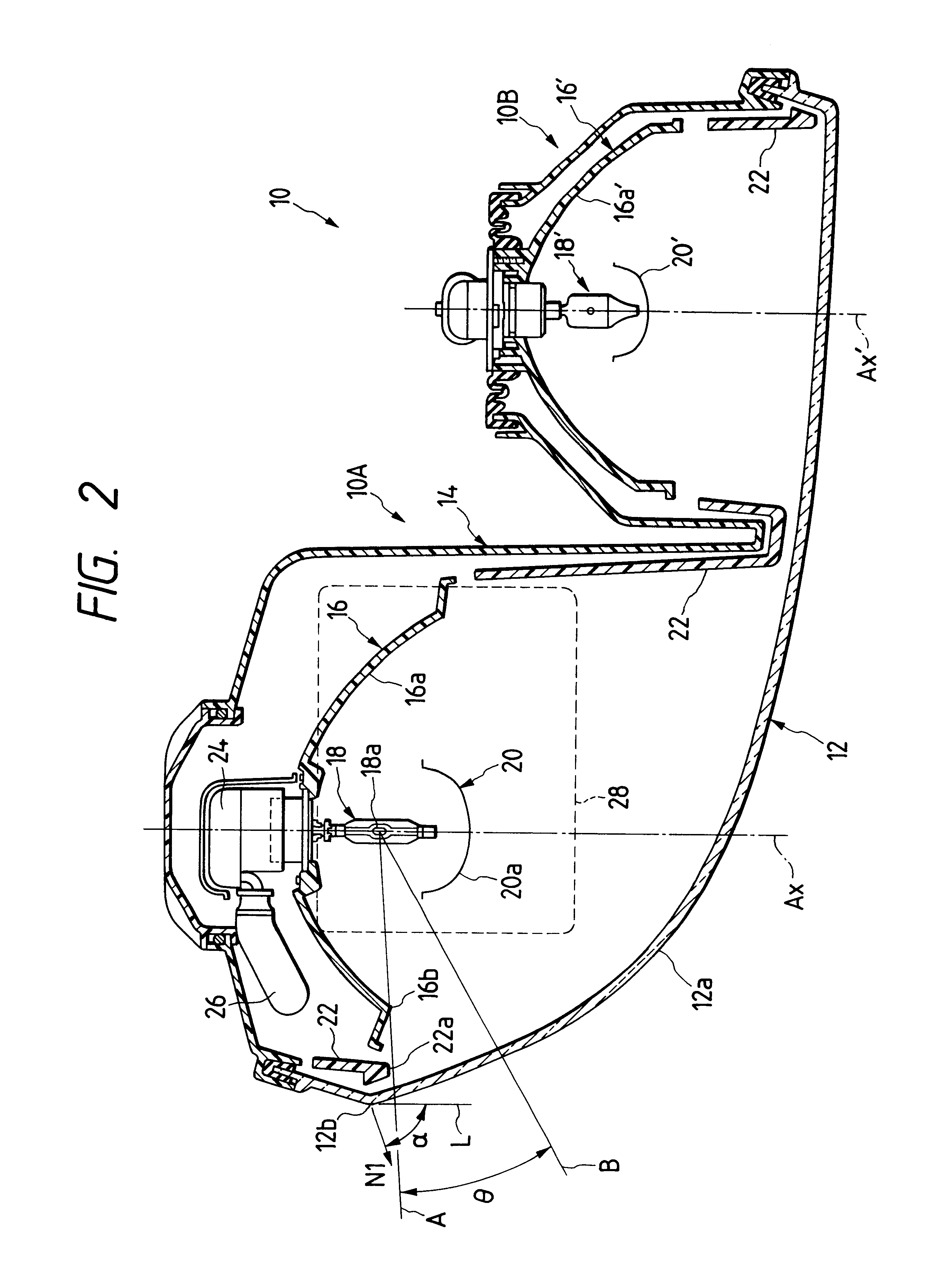
As was described above, the surface configuration of the lens is a curved configuration which is curved outwardly as viewed in the direction of width of a vehicle body and backwardly. More particularly, the normal at the outermost end, as viewed in the direction of width of the vehicle body, of the lens surface is inclined more than 45.degree. outwardly with respect to the axial line which is extended in the front-to-rear direction of the vehicle body. Hence, the sideward open angle which the straight line connecting the light emitting section of the discharge bulb to the outermost end, as viewed in the direction of width of the vehicle body, of the lens forms with the axial line extended in the front-to-rear direction of the vehicle body, can be set to a relatively large value. Therefore, in addition to the original function of the headlamp that the light beam reflected from the reflector irradiates forwardly of the vehicle, the function can be effectively performed that the direct light beam from the discharge bulb irradiates sidewardly of the vehicle thereby allowing the driver to sufficiently see the shoulder of the road.
Hence, according to the invention, in the vehicle headlamp having the discharge bulb, the great power of the latter can be effectively utilized.
In the invention, the above-described headlamp can be provided at the corner of the front of the vehicle body with ease. Accordingly, not only the headlamp body but also the lighting circuit unit adapted to turn on the discharge bulb can be arranged at the aforementioned corner. This feature increases the spaces in the engine room.
Furthermore, in the vehicle headlamp of the invention, the surface configuration of the lens is a curved configuration which is curved upwardly and backwardly, and at the uppermost end of the surface of the lens, the normal is upwardly inclined more than 45.degree. with respect to the axial line which is extended in the front-to-rear direction of the vehicle body. Hence, in a roundish vehicle such as a sport car type vehicle, the headlamp can be mounted at the corner of the front of the vehicle body with ease.
In the case where the surface of the lens is backwardly curved not only outwardly (as viewed in the direction of width of the vehicle body) but also upwardly, in the engine room a region located below the reflector is liable to become a great dead space. Therefore, it is desirable to arrange the lighting circuit unit below and near the reflector. Furthermore, in this case, the reflector or the outer surface of the lower wall of the lamp body is relatively large in area. Hence, in the case where the lighting circuit unit is mounted on the outer surface of the lower wall, its mounting range is large; that is, the mounting of the lighting circuit unit is high in the degree of freedom.
As was described above, in the case where, at the outermost end (as viewed in the direction of width of the vehicle body) of the surface of the lens or at the uppermost end thereof, the normal is inclined more than 45.degree. outwardly (as viewed in the direction of width of the vehicle body) or upwardly with respect to the axial line, in the front-to-rear direction, of the vehicle body, the above-described effects are obtained. However, if the angle of inclination is larger (for instance more than 60.degree.), then the effects are more significant.

Problems solved by technology

Hence, the lens of the conventional headlamp suffers from the following drawbacks: That is, even if the surface configuration of the lens is curved along the front configuration of the front end portion of the vehicle body; more specifically, even if it is extended outwardly as viewed in the direction of width of the vehicle body and somewhat curved backwardly, their angles of inclination to the right and left are not so large.
Hence, heretofore, although the light beam reflected from the reflector irradiates forwardly of the vehicle, it is impossible to employ a method for effectively utilizing the great power of the discharge lamp to emit a light beam directly from the discharge bulb so as to irradiate sidwardly of the vehicle body thereby allowing the driver to see a shoulder of a road sufficiently.
In the case where, as was described above, the headlamp is provided at the corner of the front of the vehicle body, the region below the reflector is liable to become a dead space.
In the case where the surface of the lens is backwardly curved not only outwardly (as viewed in the direction of width of the vehicle body) but also upwardly, in the engine room a region located below the reflector is liable to become a great dead space.
In this case, the forward direct light beam is cut which is undesirable in the light distribution of the lamp, and the direct light beam irradiates sidewardly which passes through the aforementioned sideward light passage space and through the lens.

Method used


Image

  • Vehicle headlamp having an outwardly and backwardly curved lens
  • Vehicle headlamp having an outwardly and backwardly curved lens
  • Vehicle headlamp having an outwardly and backwardly curved lens

Examples


Embodiment Construction

A vehicle headlamp, which constitutes a preferred embodiment of the invention, will be described with reference to the accompanying drawings.

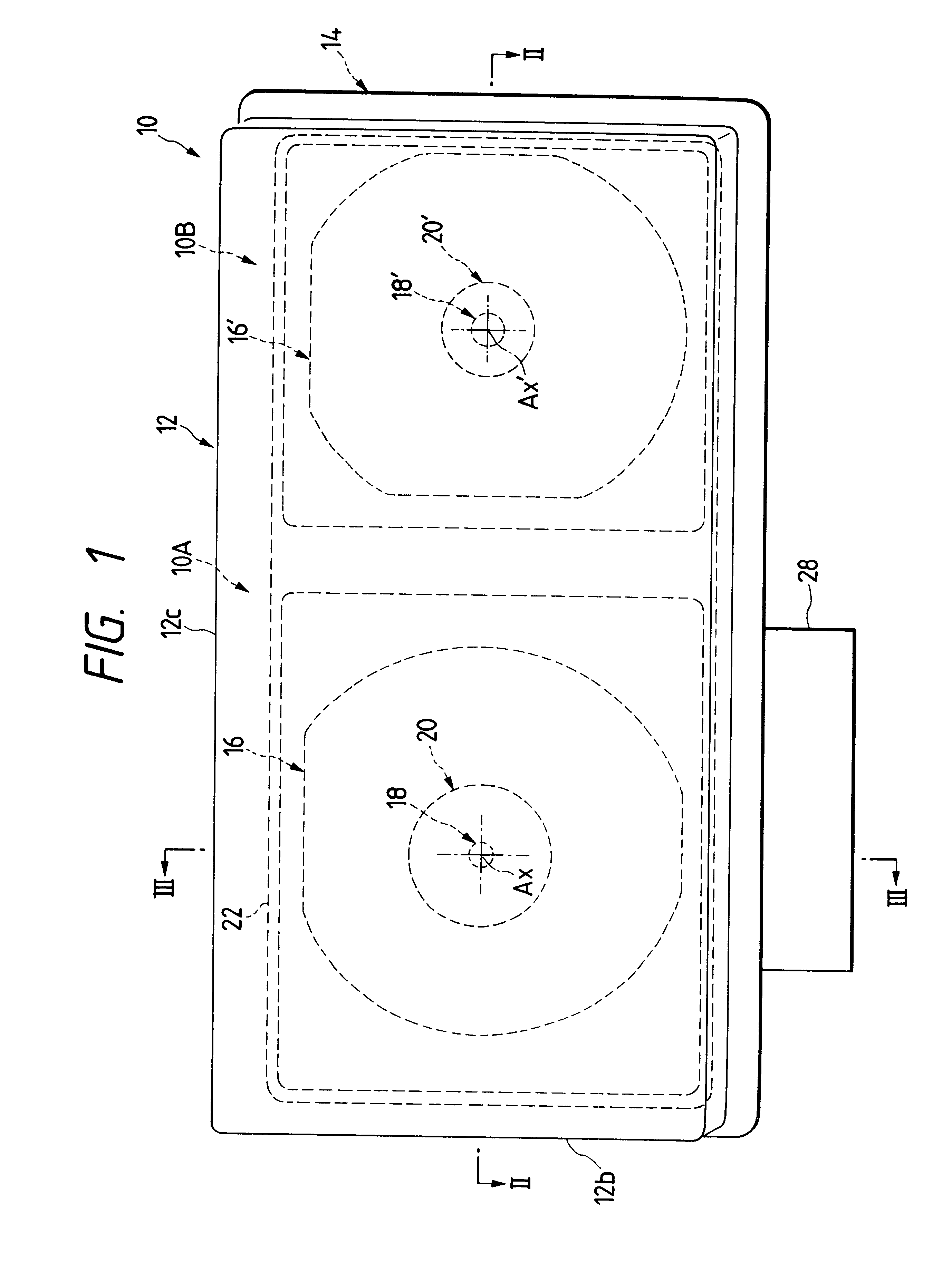
FIG. 1 is a front view of the vehicle headlamp, the embodiment of the invention. FIG. 2 is a sectional view taken along line II--II in FIG. 1. FIG. 3 is a sectional view taken along line III--III in FIG. 1.

In those figures, reference numeral 10 designates the headlamp, the embodiment of the invention. That is, the headlamp 10 is a so-called "four-lamp type headlamp, which is installed on the right side of a vehicle body. The headlamp 10 comprises two lamps 10A and 10B. With the headlamp 10, when the two lamps 10A and 10B are turned on at the same time, a main lamp light distribution pattern is formed; and when the lamp 10A is turned on, an auxiliary light distribution pattern is formed.

The lamp 10A is so designed that a lens 12 and a lamp body 14 form right and left spaces. Of the spaces thus formed, the one which is located outside as viewed i...


PUM


Abstract

The right headlamp in a four-lamp type headlamp system is provided in such a manner that its lamp having a discharge bulb which is on the outside as viewed in the direction of width of the vehicle body is positioned at the corner of the front of the vehicle body, and the configuration of the surface of the lens is a curved surface which is curved backwardly and outwardly as viewed in the direction of width of the vehicle body. Furthermore, at the outermost end, as viewed in the direction of width of the vehicle body, of the lens surface, the horizontal component of the normal thereat is inclined at an angle (=about 70°) outwardly as viewed in the direction of width of the vehicle body with respect to the axial line in the front-to-rear direction of the vehicle body. Hence, the sideward open angle can be set to a large value which the straight line connecting the light emitting section of the discharge bulb to the outermost end, as viewed in the direction of width of the vehicle body, of the lens forms with the axial line in the front-to-rear direction of the vehicle body, whereby the direct light beam from the discharge bulb is applied sidewardly of the vehicle, to allow the driver to positively observe, for instance, a shoulder of the road.

Description

1. Technical Field of the InventionThe present invention relates to a vehicle headlamp having a discharge bulb, and more particularly to the configuration of the lens of the vehicle headlamp.2. Related ArtRecently, a discharge bulb has been employed as a light source for a vehicle headlamp because it irradiates with high luminance. The discharge bulb is much higher in power than a halogen lamp or the like. Therefore, it is desirable that a headlamp with a discharge bulb performs the function of a discharge bulb sufficiently--for instance, its irradiation angle is set large.In general, a pair of headlamps are provided on the right and left of the front end of a vehicle, respectively. A front turn signal lamp or clearance lamp is provided on the outside of each of the headlamps as viewed in the direction of width of the vehicle body, and therefore the headlamps are shifted to wards the central axis of the vehicle body as much. Hence, the lens of the conventional headlamp suffers from ...

Claims


Application Information

Patent Timeline
Patent Type & Authority Patents(United States)
IPC IPC(8): B60Q1/00F21V5/00F21S8/10B60Q1/18F21V7/00F21V19/00F21W101/10F21Y101/00
CPCB60Q1/0035B60Q1/0094F21S48/1233F21S48/1186F21S48/1109F21S41/192F21S41/28F21S41/172F21S41/17
Inventor HASHIGAYA, KAZUYA
Owner KOITO MFG CO LTD
Learn More