
Monitoring catheter and method of using same

a monitoring catheter and catheter technology, applied in the field of catheters, can solve problems such as difficulty in predicting clinical deterioration or diagnosis, patient may not ventilate adequately, and conventional patient monitoring devices are incapable of easily measuring the physiological conditions of patients

Inactive Publication Date: 2001-07-10
RIC INVESTMENTS LLC
View PDF32 Cites 145 Cited by
  • Summary
  • Abstract
  • Description
  • Claims
  • Application Information

AI Technical Summary

Problems solved by technology

It is typically difficult to predict clinical deterioration or diagnose the cause of such a breathing disorder to optimize the settings on the ventilatory assist device or to determine a propitious time to initiate attempts to wean the patient from the mechanical ventilator.
Furthermore, from time to time, a patient may not ventilate adequately despite being treated with mechanical ventilation.
Conventional patient monitoring devices are incapable of easily measuring the physiological conditions of the patient needed to access the diaphragmatic function and / or inspiratory effort of the patient.
This conventional device is disadvantageous in that it only measures the pressure at one location in the patient, for example, at the distal end of the catheter.
This separate insertion procedure exposes the patient to the additional risk that the conventional pressure sensor will be unintentionally inserted into the trachea tube.
Because the major portion of the diaphgram muscle is deep within the patient's abdomen, these external EMG electrodes are often not well suited to detect diaphragm EMG signals or are contaminated by signals from the muscles overlying the abdomen, as well as the cardiac activity of the patient.
However, a suitable monitoring device using such internal EMG measurment techniques has not gained popular acceptance.

Method used


Image

  • Monitoring catheter and method of using same
  • Monitoring catheter and method of using same
  • Monitoring catheter and method of using same

Examples


Embodiment Construction

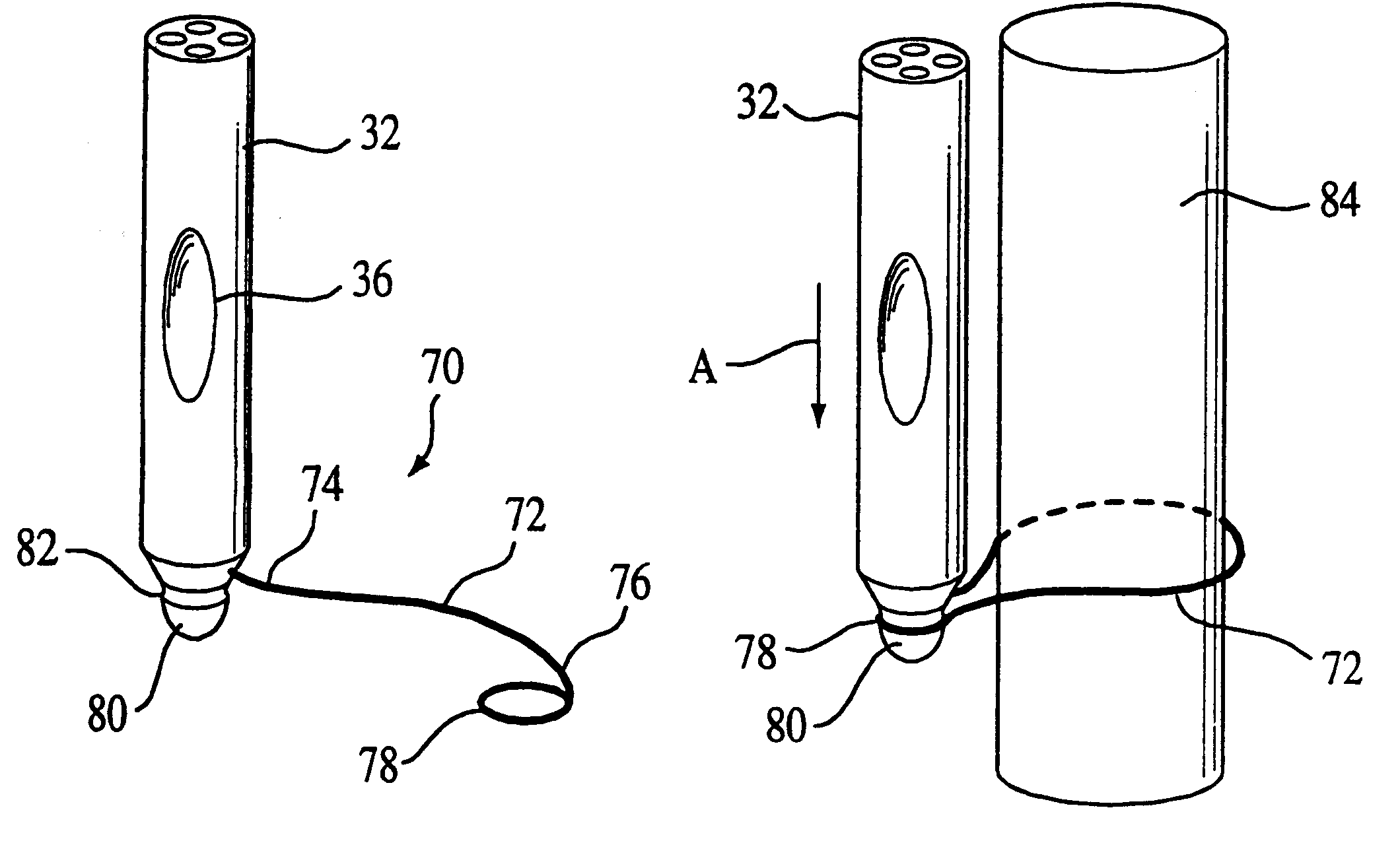
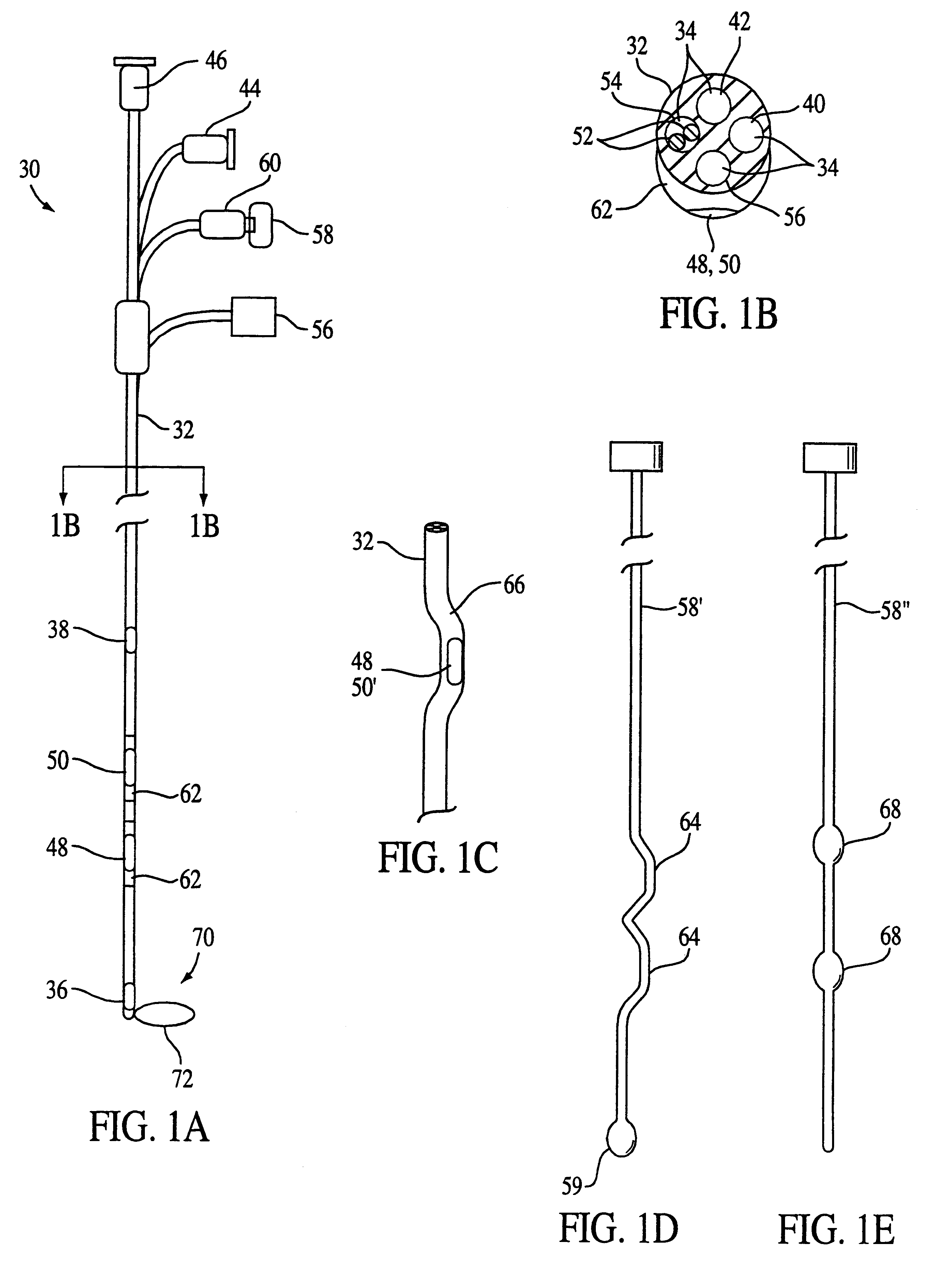
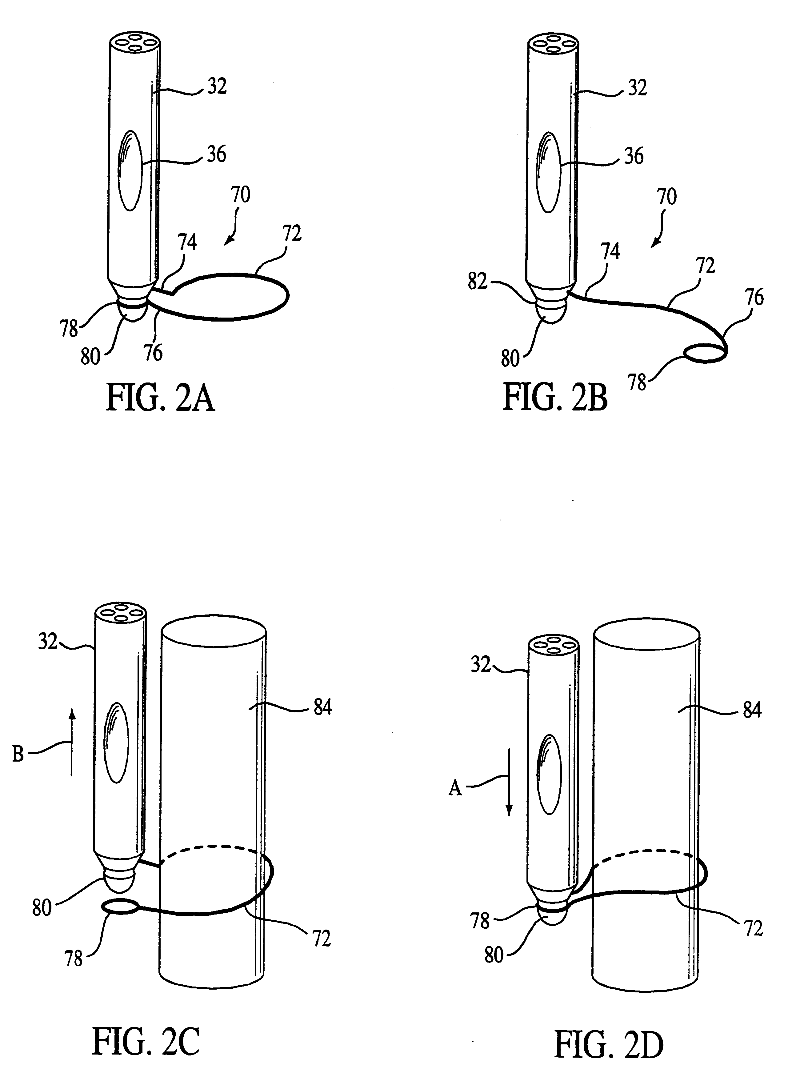
FIGS. 1A-1C illustrate a first embodiment of a monitoring catheter 30 according to the principles of the present invention. Monitoring catheter 30 inserts into the patient's esophagus and includes a body member 32 having a plurality of lumens 34 defined therein. Body member 32 is made from a biocompatible material suitable for use within the human body, such as a medical grade PVC with 35% Barium sulfate and having a durometer measurement of 90 Shore A. Other suitable materials for body member 30 include a medical grade polyurethane.

The entire length of the body member (or portions thereof) can be made from a radiopaque material to facilitate positioning the catheter in the patient. For example, a radiopaque strip can be provided down the length of the catheter. Alternatively, the radiopaque material can be provided at only the distal end portion of the body member because it is this portion of the catheter that is of primary interest while introducing the catheter into patient. The...


PUM


Abstract

A monitoring catheter that inserts into the patient's esophagus alone or in combination with an existing catheter, such as a feeding or aspiration tube. The monitoring catheter includes a pair of EMG electrodes on an exposed surface that contact the patient's esophageal wall to measure the activity of the diaphragm and / or a pair of pressure detecting mechanisms that measure the pressures within the patient at separate locations. The electrodes are sized and spaced from one another so as to maximize detection of diaphragm muscle activity while minimizing detection of noise. The pressure detecting mechanisms are sized and spaced apart to measure the patient's esophageal and gastric pressures, for example. If necessary, an attaching mechanism secures at least a portion of the monitoring catheter to the existing catheter so that the monitoring catheter uses the existing catheter as a tracking guide.

Description

1. Field of the InventionThe present invention pertains to a catheter that inserts into a patient's esophagus to measure physiological characteristics of the patient, and, in particular, to a monitoring catheter that, once inserted, measures the activity of the patient's diaphragm and / or measures pressures within the patient at multiple locations. The present invention also pertains to a method of using such a catheter to measure these physiological characteristics.2. Description of the Related ArtThere are many instances where it is important to determine a patient's diaphragmatic function and / or inspiratory effort. For example, it is not uncommon for a patient in an intensive care unit ("ICU") to have a breathing disorder that causes the patient to go into ventilatory failure and / or to have difficulty weaning from a mechanical ventilator. It is typically difficult to predict clinical deterioration or diagnose the cause of such a breathing disorder to optimize the settings on the v...

Claims


Application Information

Patent Timeline
Patent Type & Authority Patents(United States)
IPC IPC(8): A61B5/042A61B5/0408A61B7/00A61B7/02
CPCA61B5/0421A61B7/023A61B5/6856A61B5/285
Inventor ZARYCHTA, JAROSLAWSCARBERRY, EUGENE N.SANDERS, MARK H.WALKER, GREGORY L.SAUERBURGER, MARK F.
Owner RIC INVESTMENTS LLC
Learn More