
Ratchet tool holder

a tool holder and ratchet technology, applied in the direction of spanners, manufacturing tools, wrenches, etc., can solve the problems of difficult use, complicated system for reversing ratcheting direction, awkward to change ratcheting direction, etc., and achieve the effect of affecting the effect of very quickly and simply

Inactive Publication Date: 2001-07-17
HUTT HEINZ
View PDF14 Cites 26 Cited by
  • Summary
  • Abstract
  • Description
  • Claims
  • Application Information

AI Technical Summary

Benefits of technology

The general object of the present invention is therefore to provide a ratchet tool holder of the character described in which the change in the ratcheting direction can be effected very quickly and simply.
The object of the present invention is to provide a holder of the double ratcheting type to enable the die nut to cut or renew threads on bolts that are hard to reach or are immovable and to then retrieve the die.
Yet, another object of the invention is to provide a ratchet tool holder of the character described which is of simple construction and made of a minimum of molded parts.

Problems solved by technology

However, their system to reverse the ratcheting direction is very often complicated and difficult and awkward to use.
In all these known prior arrangements, it is rather awkward to change ratcheting direction, a serious drawback when this direction must be changed frequently during use.

Method used


Image

  • Ratchet tool holder
  • Ratchet tool holder
  • Ratchet tool holder

Examples


Embodiment Construction

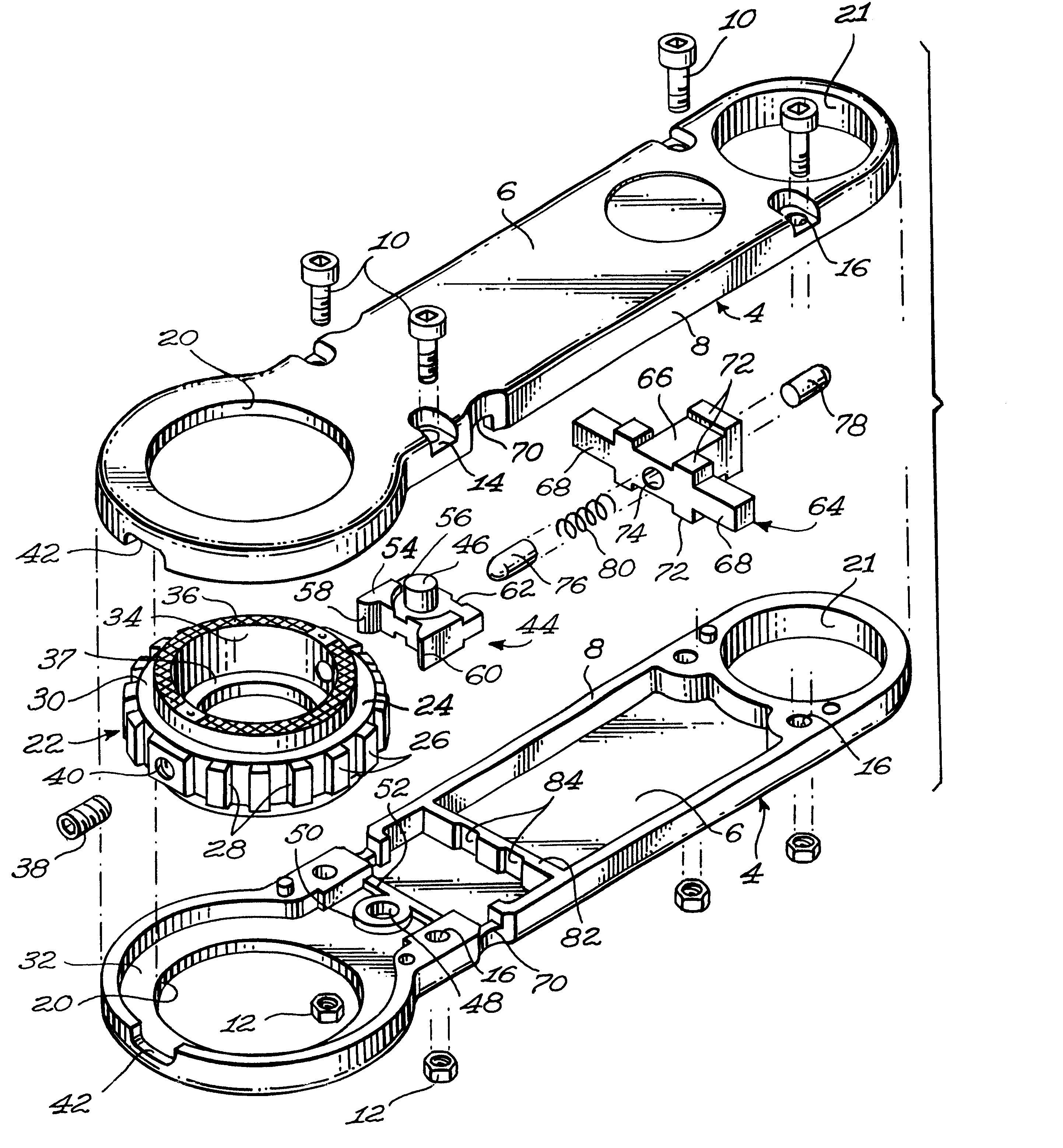
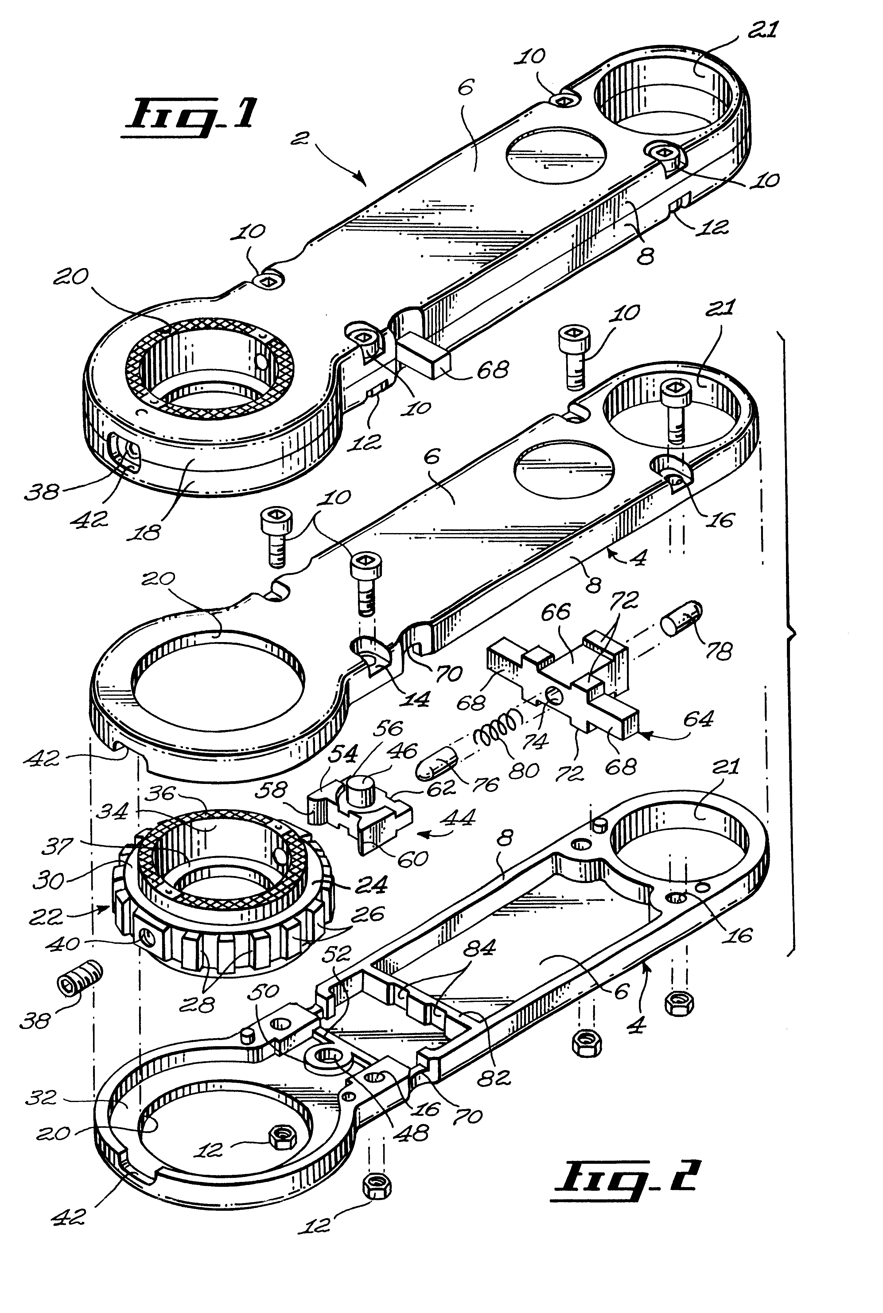
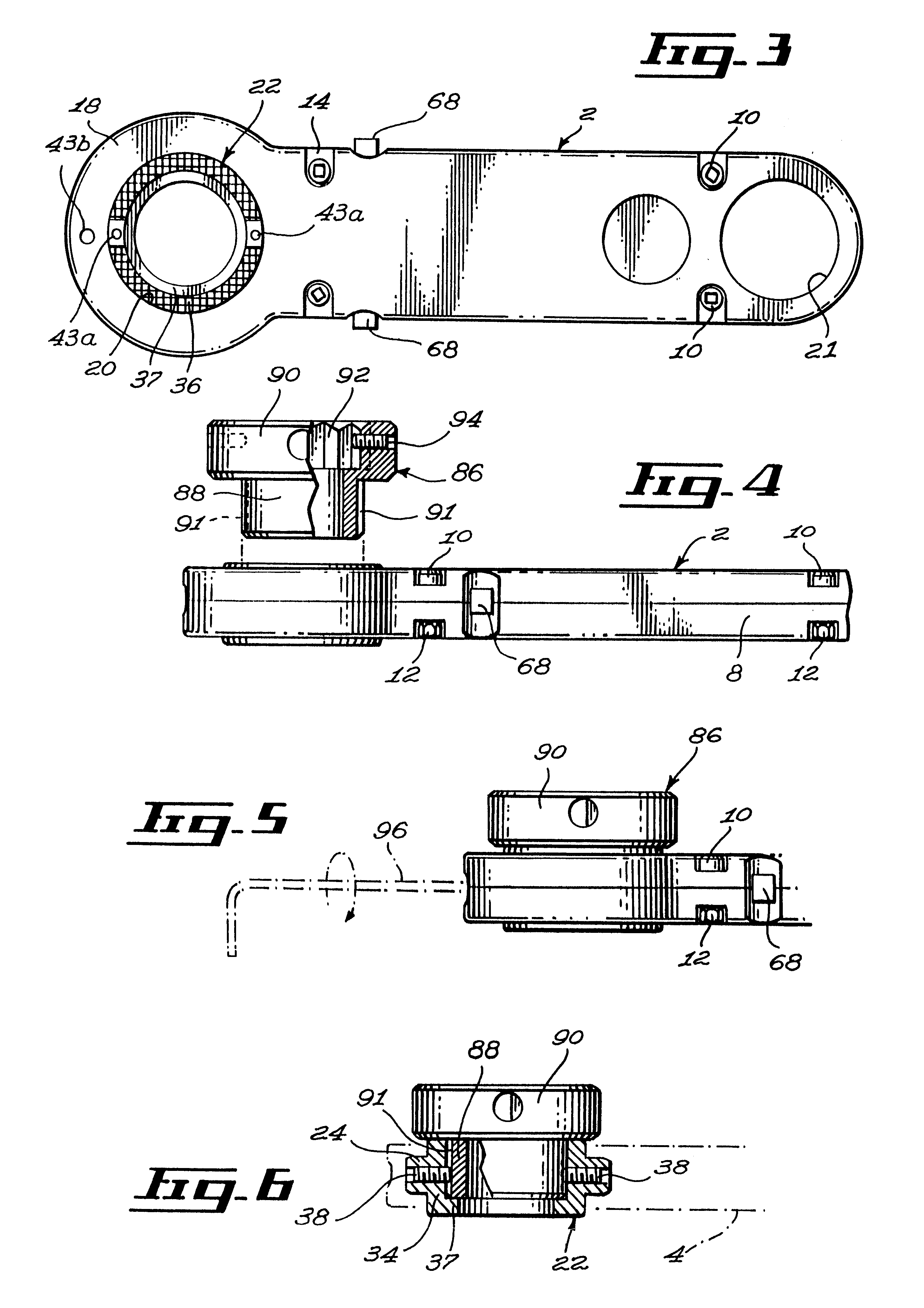
The ratchet tool holder 2 of the present invention includes two molded half handle sections 4 of identical shape and each defining a main wall 6 and a peripheral wall 8. The two half sections 4 are secured together to form a hollow handle by means of bolts 10 and nuts 12. The bolts heads or nuts 12 engage cavities 14. The cavities 14 surround holes 16 for receiving the bolts 10.

Each half handle section 4 has an enlarged end 18 forming a thru opening 20; an opening 21 at the other end serves to hook the tool to a support when not in used.

An annular ratchet gear 22 is rotatably mounted within enlarged end 18 in register with thru opening 20. Ratchet gear 22 has a central rib 24 formed with a gear teeth 26 of symmetrical shape, each tooth having two opposites similar radial faces 28. The central rib 24 has opposite side faces 30 which rest on the main wall portion 32 which surrounds thru opening 20. Gear 22 has a cylindrical body 34 fitted in each thru opening 20 of the two half handle...


PUM


Abstract

An elongated hollow handle forms a circular thru opening at one end. An annular ratchet gear is rotatably mounted within the handle and exposed in this opening and is adapted to carry a tool such as a die nut releasably secured within the gear and exposed thru opening. A double acting swivel pawl is centrally pivoted within the hollow handle and has two spaced pawl projections equally spaced from the pivot axis of the swivel pawl. A. transversely movable slider has opposite push buttons alternately protruding from the sides of the hollow handle; this slider has a spring bias plunger adapted to engage alternately opposite notches made in the rocker member on each side of its pivot axis. Therefore, a simple push on the protruding push button will change the direction in which the gear is rotated when swinging the handle back and forth. The gear has knurled exposed surfaces to enable manual grasping of the gear to brake its rotation during ratcheting.

Description

The present invention relates to a ratchet tool holder more particularly designed for holding die nuts or taps. The holder is of the type which can rotate the tool in any direction with ratcheting in the opposite direction.Tool holders of the double ratcheting type have been known for a long time. However, their system to reverse the ratcheting direction is very often complicated and difficult and awkward to use.For instance, in U.S. Pat. No. 270,516 dated Jan. 9, 1883 to Turner and entitled "Ratchet Drill", to change ratcheting direction, the levers A on each side of the handle M must be operated to selectively actuate two different pawls P.In U.S. Pat. No. 828,026 dated Aug. 7, 1906 to Garrigus and Golling and entitled "Tool Holder", the pawl member 7, 8 must be rotated about its longitudinal axis through 180.degree. in order to change ratcheting direction.In U.S. Pat. No. 929,036 dated Jul. 27, 1909 to Smith and entitled "Ratchet Die-Stock", there are two pawl members 20 located ...

Claims


Application Information

Patent Timeline
IPC IPC(8): B25B13/00B25B13/46
CPCB25B13/463
Inventor HUTT, HEINZ
Owner HUTT HEINZ
Learn More