Wireless Transmission of High Quality Video

a high-quality, still-and-video technology, applied in the field of wireless transmission of high-quality still-and-video images, can solve the problems of complex hardware for implementing compression, inapplicability to home appliances, and general undesired connection of screen to set-top box through cable, so as to achieve simple compression hardware, improve compression results, and simplify the compression procedure

Inactive Publication Date: 2008-05-29
AMIMON
View PDF25 Cites 54 Cited by
  • Summary
  • Abstract
  • Description
  • Claims
  • Application Information

AI Technical Summary

Benefits of technology

[0038]An aspect of some embodiments of the invention relates to dividing transmitted video signals into a coarse portion and a refinement portion, for superimposed transmission, such that the coarse portion is compressed using a near-lossless compression method having a compression ratio of less than 1:15, on typical images of the original video images. In some embodiments of the invention, the compression ratio is less than 1:10, for example about 1:8. Although in the prior art it was considered that it would be better to use a stronger compression and hence fit more data content on the available bandwidth, in accordance with some embodiments of the present invention a near lossless compression with a refinement portion is used. Using a near lossless compression allows for a simpler compression procedure and hence simpler compression hardware. In addition, the refinement portion may be transmitted, in some embodiments of the invention, using noisy bandwidth which could not be used efficiently for transmission of the coarse portion.
[0039]An aspect of some embodiments of the invention relates to compressing video signals for transmission b...

Problems solved by technology

Connection of the screen to the set-top box through cables is generally undesired for aesthetic reasons and/or installation convenience and wireless transmission of the video signals from the set-top box to the screen is preferred.
Known strong video compression methods (e.g., having a compression factor of above 1:30) require very complex hardware for implementing the compression, which is not practical for home apparatus.
Alternatively or additionally, strong video compression methods have a relatively high image degradation, which is unacceptable for high quality video display.
The known strong video compression methods also suffer from high sensitivity to transient noise and fading, such that an entire frame or even more may be lost due to a short fading period.
One reason that this is not implemented is that the content...

Method used


Image

  • Wireless Transmission of High Quality Video
  • Wireless Transmission of High Quality Video
  • Wireless Transmission of High Quality Video

Examples


Embodiment Construction

System Overview

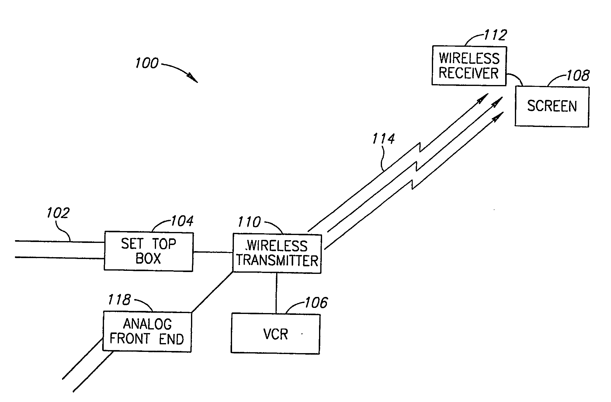
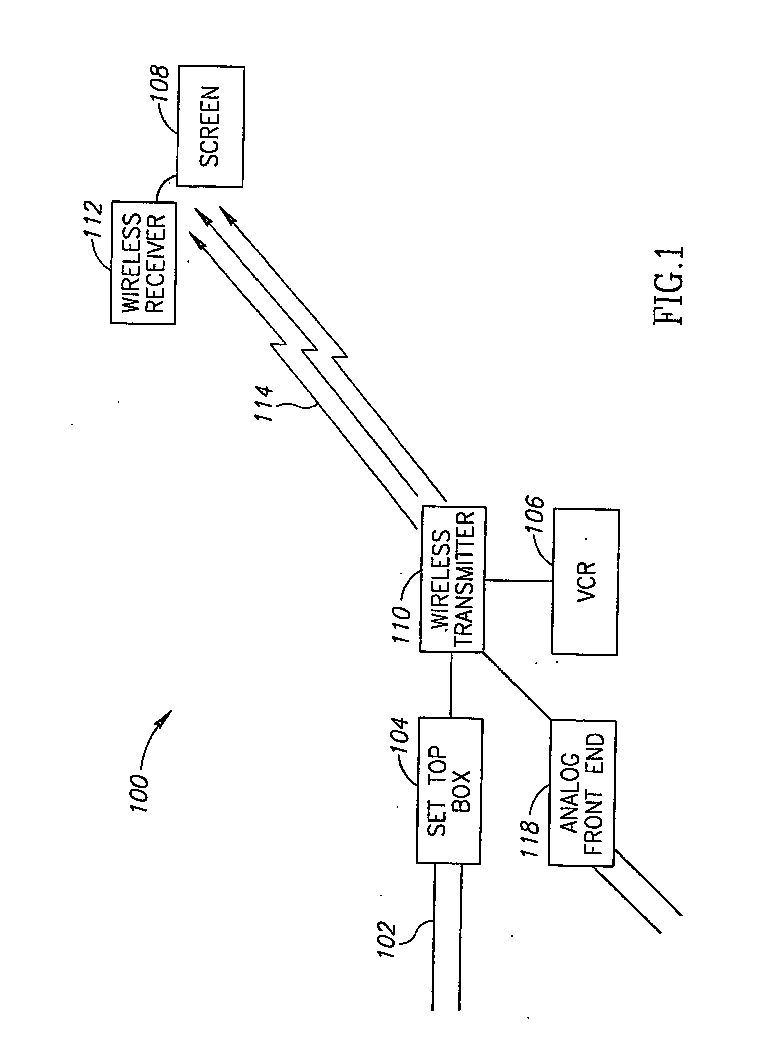
[0094]FIG. 1 is a schematic illustration of a wireless transmission system 100, in accordance with an exemplary embodiment of the invention. System 100 comprises a wireless transceiver 110 which receives video signals from a set-top box 104, a VCR 106, a game box, a DVD and / or any other video signal source, for example through an analog front end 118. The video signals are compressed and encoded by wireless transmitter 110 and transmitted on a wireless link 114 to a wireless receiver 112. Wireless receiver 112 decompresses and decodes the signals for display on a screen 108.

[0095]Set-top box 104 optionally receives the video signals in a standard format, such as HDTV or SDTV, from a video source, over cables 102. In some embodiments of the invention, the video signals received through cables 102 are encrypted and compressed by the video source and are decompressed and decrypted by set-top box 104. Wireless transmitter 110 generally receives the video signals after dec...


PUM


Abstract

A method of transmitting video images. The method includes providing a high definition video stream, compressing the video stream using an image domain compression method, in which each pixel is coded based on a vicinity of the pixel and transmitting the compressed video stream over a fading transmission channel.

Description

RELATED APPLICATIONS[0001]The present application claims the benefit under 35 USC 119 (e) of U.S. Provisional Applications No. 60 / 505,439 filed Sep. 25, 2003, 60 / 508,061 filed Oct. 2, 2003 and 60 / 590,197 filed Jul. 21, 2004, the disclosures of which are incorporated by reference.FIELD OF THE INVENTION[0002]The present invention relates generally to wireless transmission of high quality still and / or video images and particularly to high quality wireless transmission of images in relatively noisy and / or fading environments.BACKGROUND OF THE INVENTION[0003]In many houses, television and / or video signals are received through cable or satellite links at a set-top box at a fixed point in the house. In many cases it is desired to place a screen at a point distanced from the set-top box by a few meters. Connection of the screen to the set-top box through cables is generally undesired for aesthetic reasons and / or installation convenience and wireless transmission of the video signals from th...

Claims


Application Information

Patent Timeline
IPC IPC(8): H04N7/26H04HH04J99/00H04N7/167H04N7/18H04N7/24
CPCH04B7/0669H04B7/08H04L27/2604H04L27/3488H04N7/1675H04N21/631H04N21/23476H04N21/2383H04N21/2385H04N21/4382H04N21/44055H04N21/234327H04N19/40H04N19/59H04N19/625
Inventor REZNIC, ZVIGERI, NOAM
Owner AMIMON
Why Eureka
Try Eureka