Extension housing for RF multi-tap

a multi-tap and extension housing technology, applied in the direction of coupling device details, television system, coupling device connection, etc., can solve the problems of adding additional insertion loss into the circuit, affecting the performance of extension coaxial connectors, and affecting the connection point performan

Inactive Publication Date: 2001-07-17
LANTEK USA
View PDF6 Cites 24 Cited by
  • Summary
  • Abstract
  • Description
  • Claims
  • Application Information

AI Technical Summary

Problems solved by technology

Extension coaxial connectors typically perform poorly.
The additional connector in series adds additional insertion loss into the circuit and th

Method used


Image

  • Extension housing for RF multi-tap
  • Extension housing for RF multi-tap
  • Extension housing for RF multi-tap

Examples


Embodiment Construction

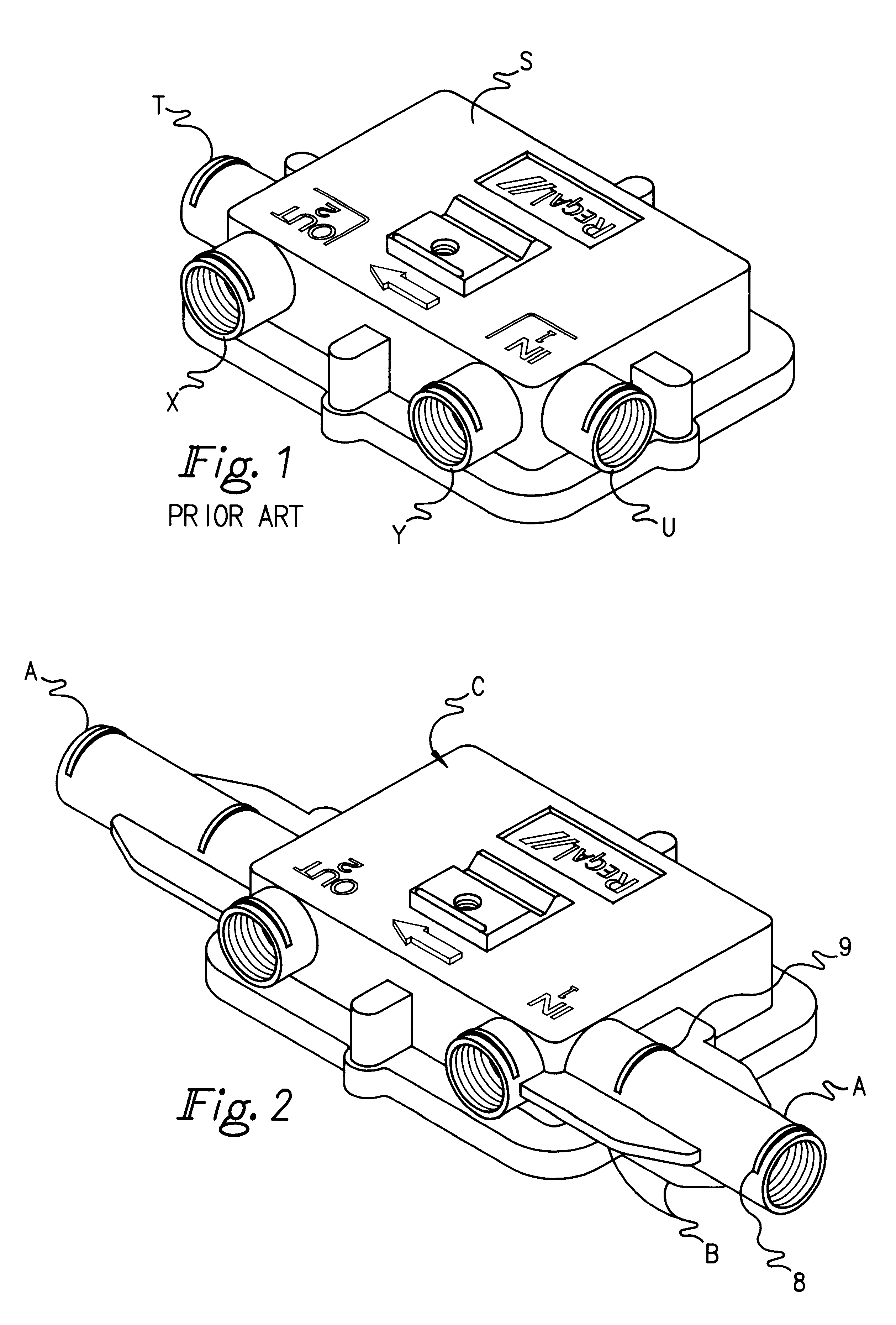
There is shown by way of illustrative example in FIG. 1 a conventional multi-tap housing including a main housing S, a first connecting portion T and a second connecting portion U, the connecting portions T and U being tubular and disposed at opposite ends of the housing 1. First and second fixed tubular portions X and Y are mounted on one side of the shell at right angles to the connecting portions T and U, respectively.

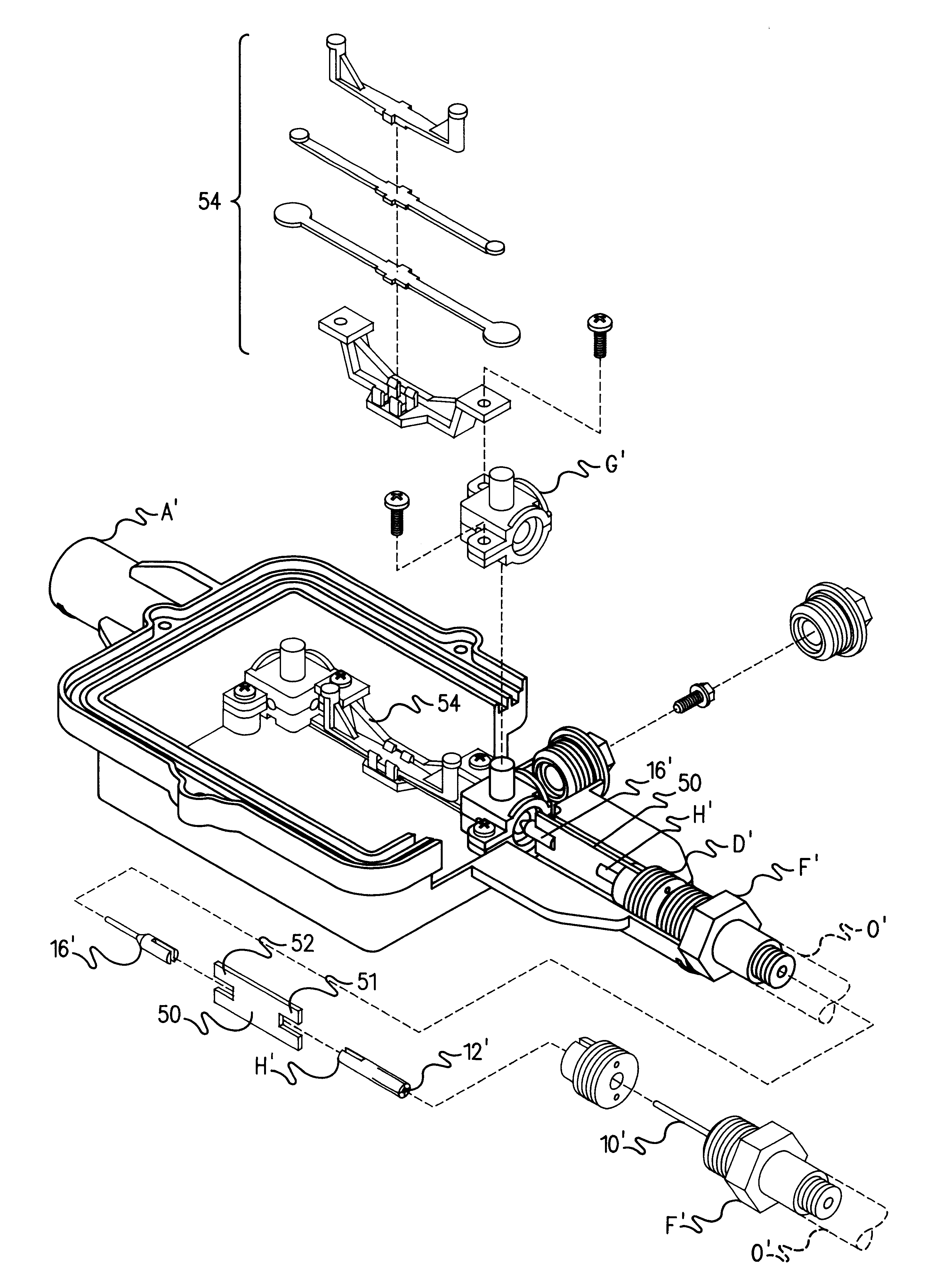
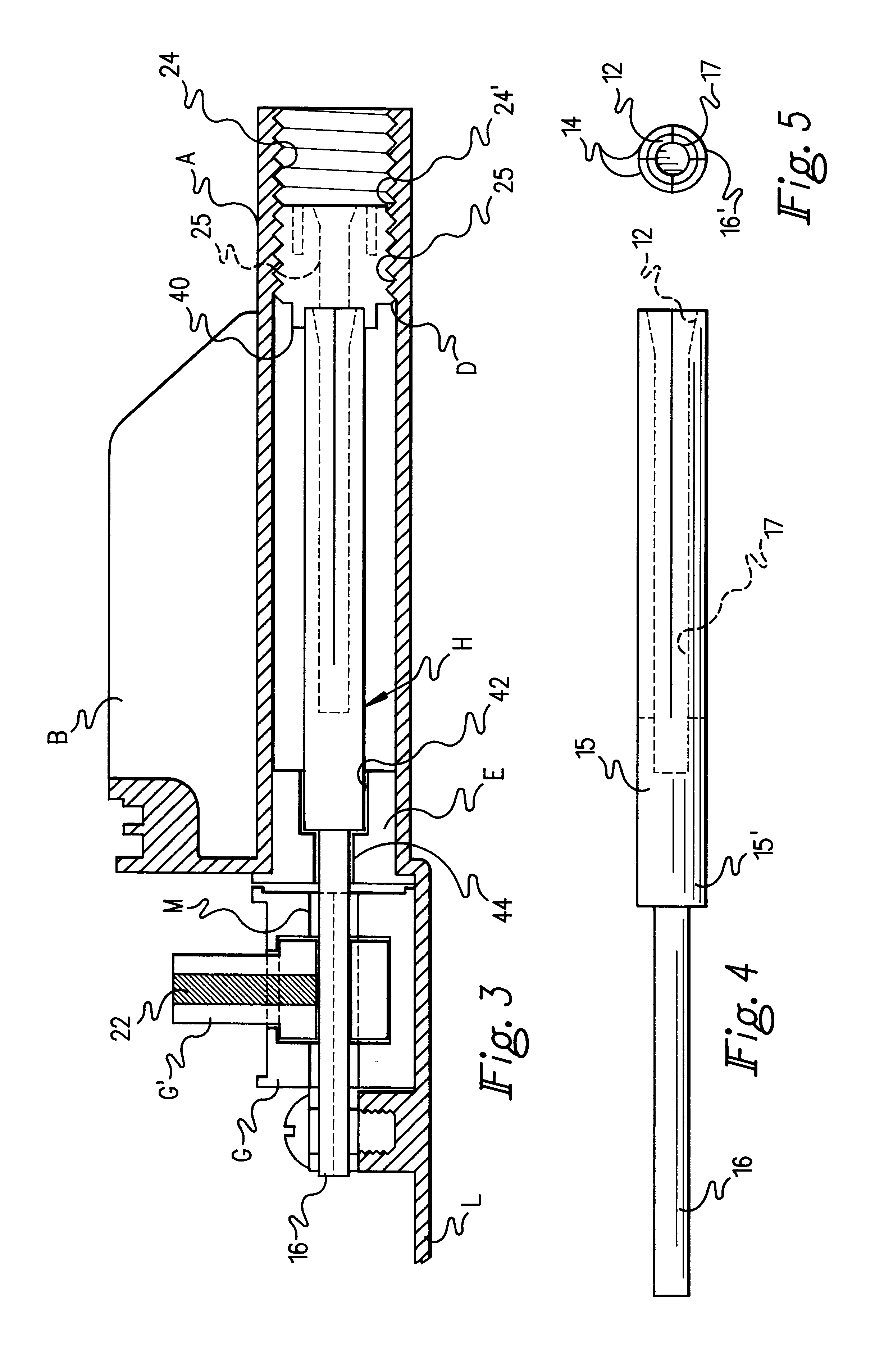
Referring in more detail to FIGS. 2 to 6, one form of invention is illustrated wherein an extension housing C spans a distance between coaxial cable ends which will compensate for the increased separation resulting from removal of the existing tap assembly. For example, the extension housing C is on the order of 9" from end to end and is broadly comprised of a main body or housing proper L and spaced coaxial grounded housing ports or tubes A. Each Tube A is provided with a stopping portion 8 and a measuring portion 9. Each of the portions 8 and 9 is raised slightly,...


PUM


Abstract

An extension housing (C) for a cable TV multi-tap device is made up of extension tubes (A) in coaxially aligned relation to one another for the purpose of providing wider bandwidth subscriber multi-taps with a longer extension coaxial connector to span the distance between a TV coaxial cable ends without affecting performance. An RF signal connector (H) is inserted in each tube having a dielectric insulator (D) at one end, an elongated conductor (15) having a bore (17) extending through its greater length and longitudinally split segments (14) surrounding the bore for insertion of a conductor pin (10) extending from a cable connector at the end of the extension tube and inserted through the dialectric insulator into the bore and a second conductor pin (16) extending from the elongated conductor into contact with a face plate connector (G) in the housing. In one form of invention the second conductor pin extends through a second dielectric insulator (E) into contact with the face place connector. In another form of invention, a printed circuit board (50) is interposed between the second conductor pin (10') and the connector (H') to establish a predetermined impedance in the RF signal connector.

Description

BACKGROUND AND FIELD OF INVENTIONThis invention relates to RF signal distribution devices and more particularly relates to a novel and improved extension housing for multi-taps employed in the field of cable television.As the traditional cable television providers offer new advanced services throughout the existing network of transmission plants, it is often necessary to upgrade each plant with wider bandwidth subscriber multi-taps. In doing so, it is desirable to replace the electronics and the coaxial connectors but leave the existing coaxial cable in place. The common practice is to cut the existing connectors and the electronics out of the circuit, and then to utilize new subscriber multi-taps of wider bandwidth and a longer "extension" coaxial connector to span the distance between coaxial cable ends.Extension coaxial connectors typically perform poorly. The additional connector in series adds additional insertion loss into the circuit and the added connection points add increa...

Claims


Application Information

Patent Timeline
IPC IPC(8): H01R9/05H01R13/00H01R13/646H01R13/66H04N7/10H01R24/54
CPCH01R9/0509H01R13/6658H04N7/104H01R24/547H01R2105/00
Inventor YEH, TONY
Owner LANTEK USA
Why Eureka
Try Eureka