

Circuit device
- Summary
- Abstract
- Description
- Claims
- Application Information
AI Technical Summary
Benefits of technology
Problems solved by technology
Method used
Image

Examples
Embodiment Construction
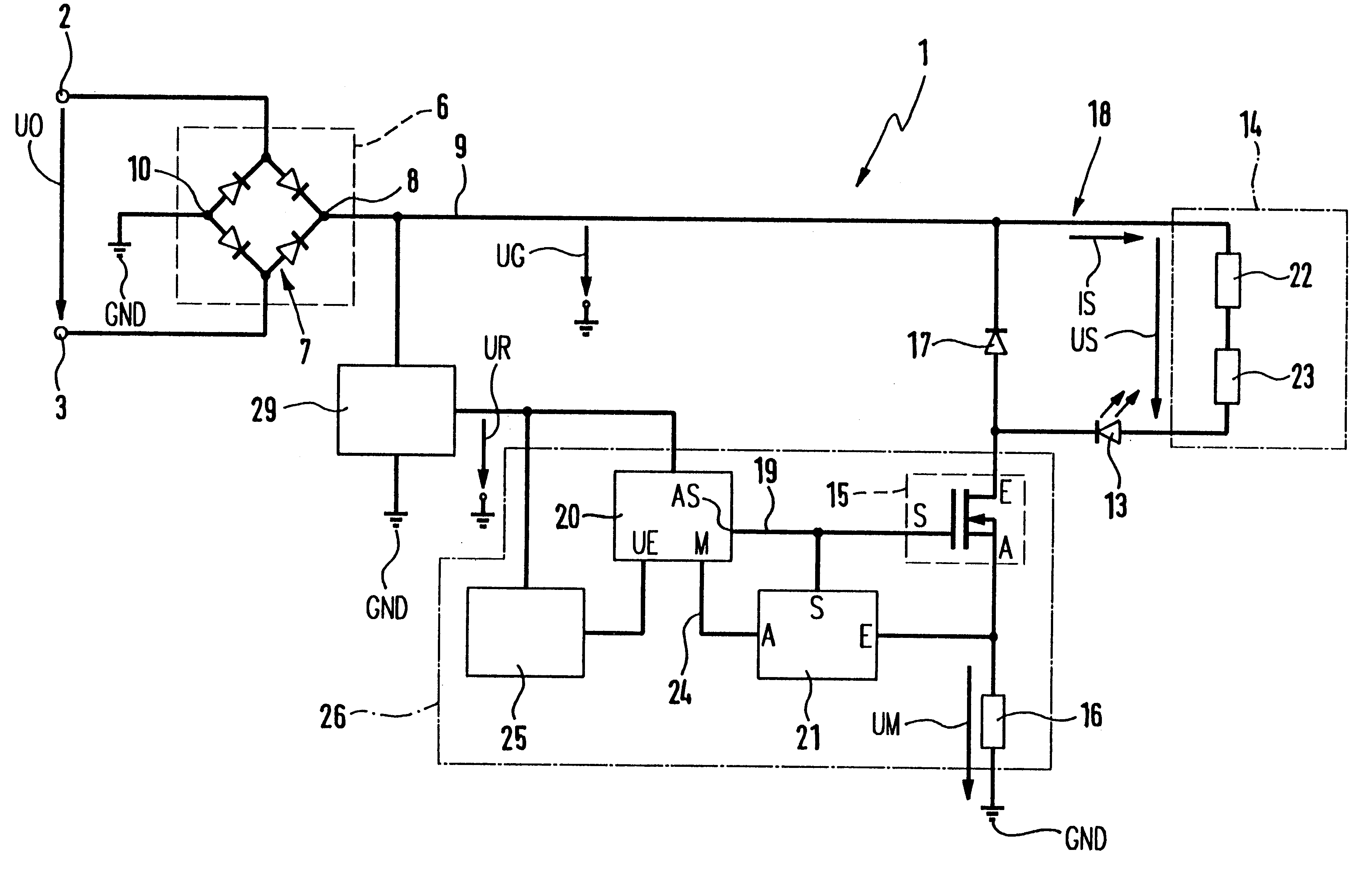
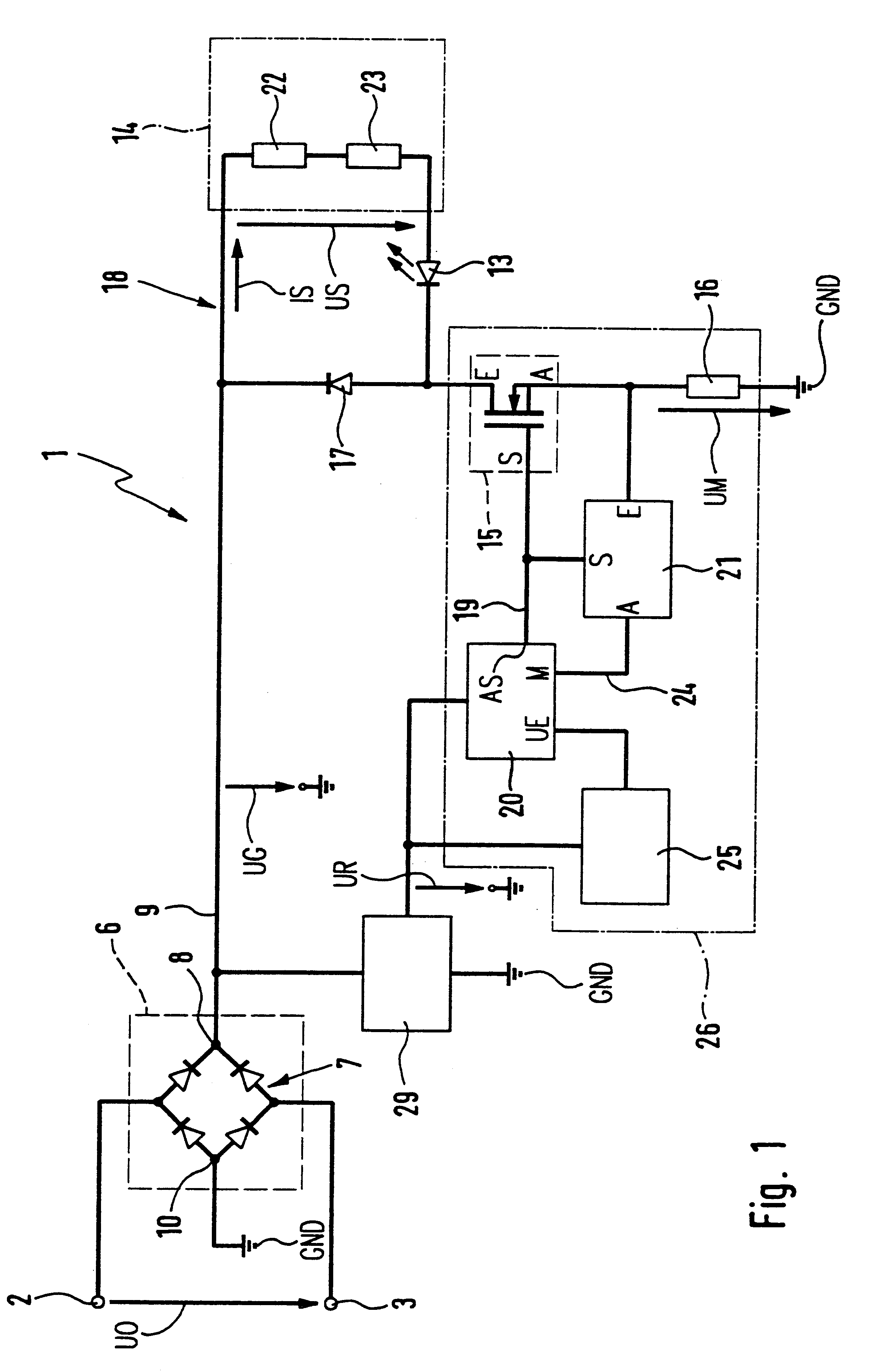
FIG. 1 shows a working embodiment of the circuit device 1. The circuit device 1 comprises two input terminals 2 and 3, to which an input voltage UO may be applied. The input terminals 2 and 3 are connected with a rectifier arrangement 6, which for example is constituted by a diode bridge circuit 7. By means of the rectifier arrangement constituted by the diode bridge circuit the input voltage UO is converted into the supply direct voltage UG. The plus pole of the supply direct voltage U is connected with a positive output 8 of the rectifier arrangement 6, which is connected with a supply line 9, and negative output 10 of the rectifier arrangement 6, which is connected with the minus pole of the supply direct voltage, is connected with the ground potential GND (0 volt). Between the supply line 9 and the ground potential GND the supply direct voltage UG is present.
As a modification of the preferred embodiment in accordance with FIG. 1 it is possible to provide a smoothing capacitor.
Th...
PUM
 Abstract
Description
Claims
Application Information