Eureka AIR delivers breakthrough ideas for toughest innovation challenges, trusted by R&D personnel around the world.

Heat exchanger and method of producing the same

Inactive Publication Date: 2001-07-24
WALEO ENGINE COOLING
View PDF24 Cites 37 Cited by
  • Summary
  • Abstract
  • Description
  • Claims
  • Application Information

AI Technical Summary

Benefits of technology

Another object is to produce a heat exchanger which can be assembled for soldering in one stage in a rapid, simple, very accurate manner with low requirements on the tolerances of the individual parts.
A further object of the invention is to produce a heat exchanger which allows manual repair of leaking joints after it has been soldered together.
It is likewise an object to produce a heat exchanger having reduced risk of generating turbulence in the transition between tube and tank.
According to a further aspect of the invention there is provided a method of connecting flat liquid-conveying tubes to a connection plate in the production of a heat exchanger. A plurality of holes are formed in the connection plate and are deformed in such a manner that tube-accommodating connecting sleeve elements are formed on the one flat side of the plate. One end area of each tube is, in a first step of deformation, deformed in such a manner as to obtain a shape corresponding to that of the connecting sleeve element, thereby increasing the cross-sectional area of the end area. The end area is, in the first step of deformation, given smaller dimensions than the connecting sleeve element. The widened end areas of the tubes are, from the one flat side, inserted in the connecting sleeve elements until the end surfaces of the tubes are located essentially on a level with the holes of the plate. The widened end areas of the tubes are, in a second step of deformation, further widened from the other flat side of the plate in such a manner that the respective tube ends are applied against a transitional area located between the plate and the respective connecting sleeve elements.
The method according to the invention reduces the risk of leakage in the heat exchanger produced, as a solder layer is applied to a solder layer in the joints between the connecting sleeve elements and the tubes. As a result, the quantity of solder material which is available during brazing is increased.
The inside of the tube is completely smooth at the transition between the tube and the tank, which minimizes the occurrence of turbulence.

Problems solved by technology

These are expensive, however, and moreover conduct heat away from those parts which are to be soldered together.
Furthermore, it is a time-consuming process to fix the parts of the heat exchanger with great accuracy using external fixtures, which makes the production more expensive.
In the production of radiators of the above type, it has emerged that, in spite of the use of external fixtures, a large number of radiators leak, after brazing, at the joints between the tubes and the connecting sleeve elements, as a result of which up to approximately 20% of radiators have had to be rejected, since the leakage detected cannot be repaired manually after brazing.
Furthermore, the connecting sleeve elements can cause turbulence and retard liquid flow through the tubes.

Method used


Image

  • Heat exchanger and method of producing the same
  • Heat exchanger and method of producing the same
  • Heat exchanger and method of producing the same

Examples


Embodiment Construction

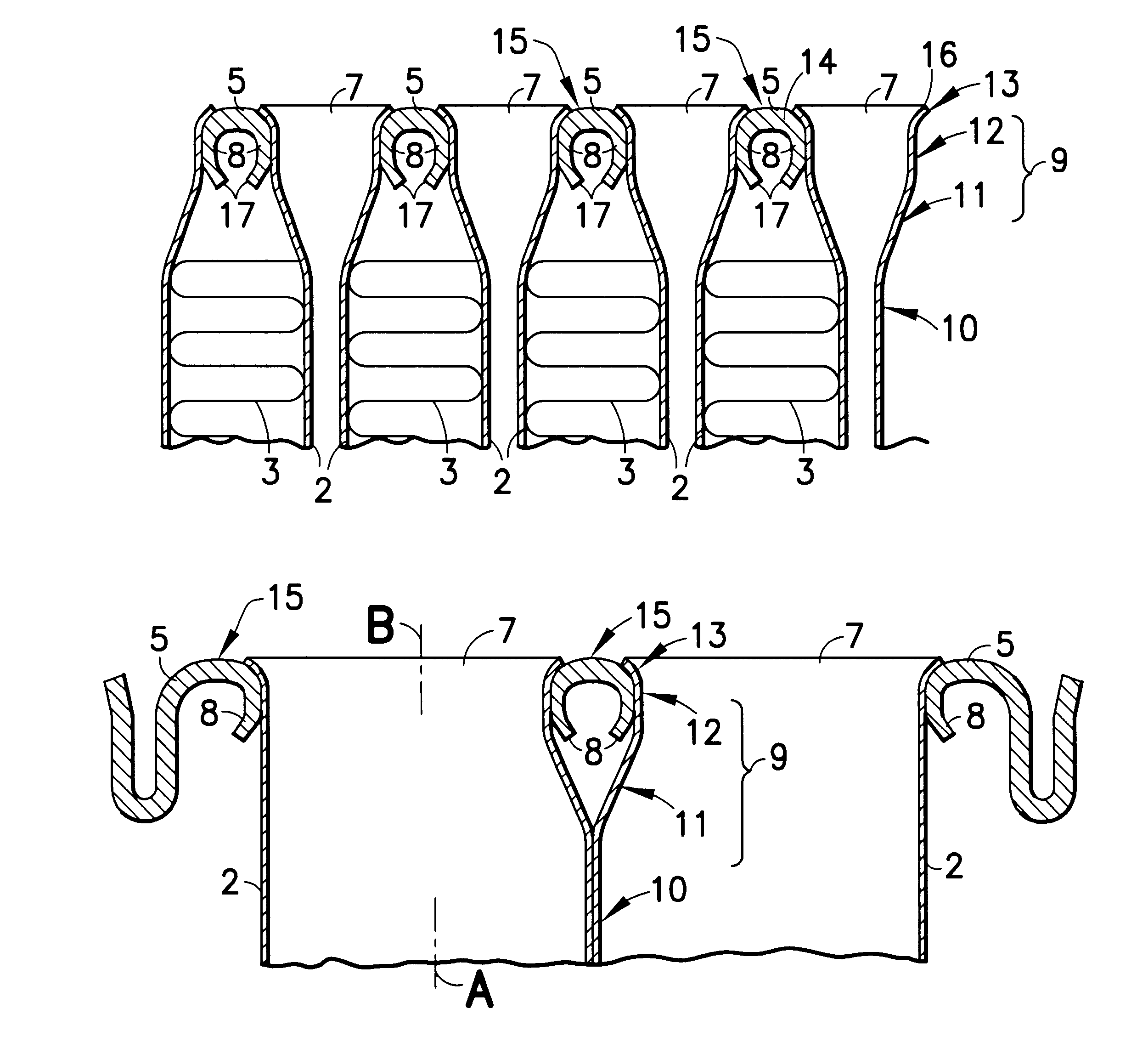
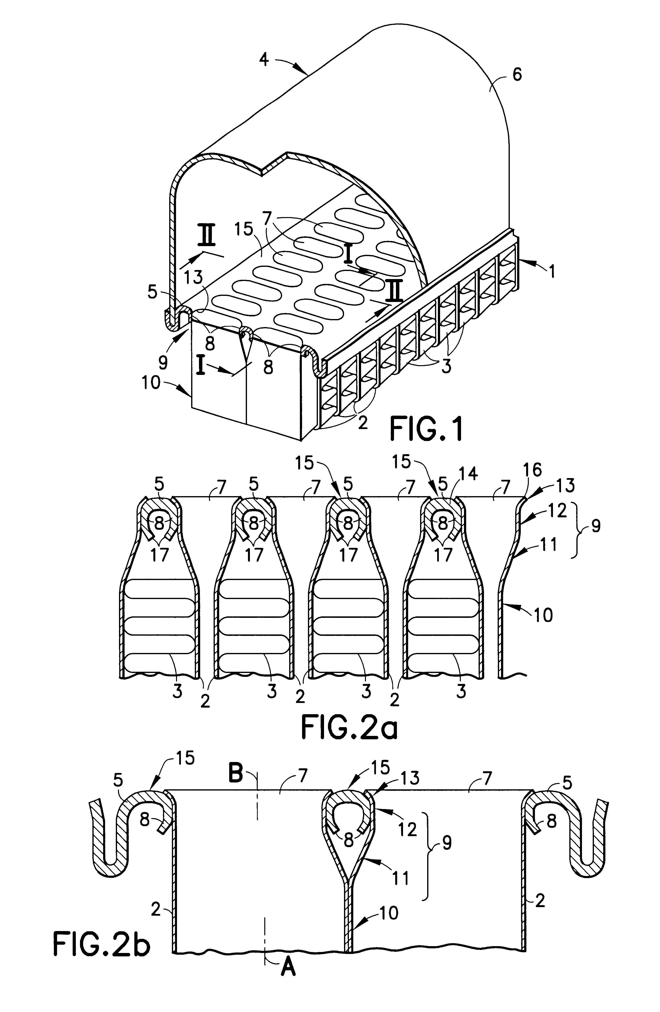
The heat exchanger according to FIG. 1 has a heat-exchanger assembly 1 with two essentially parallel rows of flat liquid-conveying tubes 2 made of aluminum. The heat-exchanger assembly 1 also has surface-enlarging means 3, so-called ranks, which extend over the width of the heat-exchanger assembly 1 and which are arranged between each pair of tubes 2 in the respective row. The tubes 2 are arranged flat side to flat side in each row. An inlet tank 4, which comprises a connection plate 5 made of aluminum and a cover 6 connected to the plate 5, is connected to a first end of the heat-exchanger assembly 1. A corresponding outlet tank (not shown) is connected to the second, opposite end of the heat-exchanger assembly 1. The fastening of the cover 6 to the plate 5 is not significant for the invention and is not described any further.

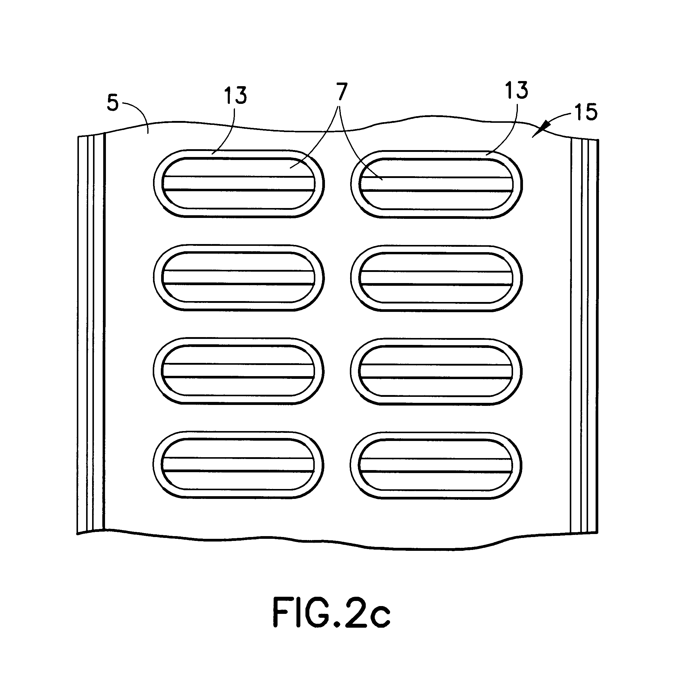
The connection plate 5 is provided with parallel first and second rows of oblong holes 7 which, in the transverse and longitudinal directions, are situated at...


PUM

PropertyMeasurementUnit
Shapeaaaaaaaaaa
Widthaaaaaaaaaa
Areaaaaaaaaaaa

Abstract

A heat exchanger for vehicles comprises firstly a heat-exchanger assembly consisting of flat liquid-conveying tubes and surface-enlarging means, secondly an inlet tank, and thirdly an outlet tank. The inlet tank and the outlet tank have a connection plate with a number of connection holes for the tubes. At each hole, the plate has a projecting connecting sleeve element. Each tube has at its ends a widened main portion which is accommodated on said connecting sleeve element. A rounded transitional area is formed between the connection plate and each connecting sleeve element, and the main portion is inserted in the conecting sleeve element and is applied with its outside against the inside of the connecting sleeve element. Each tube has at its ends an end portion which is widened in relation to the main portion, merges with the main portion and is applied against the transitional area. In a method of producing such a heat exchanger, the widened end area of the tubes are inserted in the connecting sleeve elements and are widened further in such a manner that each tube end is applied against the transitional area between the plate and the respective connecting sleeve element.

Description

The present invention relates to a heat exchanger, in particular a water or air radiator for a vehicle, and the like. More particularly, the invention also relates to a method of producing the same.PRIOR ARTA common area of application for heat exchangers is cooling of circulating liquids in motor vehicles and machine tools, e.g. the liquid which cools the engine block. Heat exchangers are also used, for example, for cooling the intake air which is to be combusted in the engine of the vehicle.A vehicle radiator is known through Swedish patent 9202819. The radiator is made of aluminum and has a heat-exchanger assembly which consists of surface-enlarging means and two rows of flat liquid-conveying tubes which are arranged flat side to flat side in the respective row. The surface-enlarging means are arranged between each pair of tubes in the respective row and are intended to guide an air flow through the heat-exchanger assembly in the transverse direction of the tube rows. The radiato...

Claims


Application Information

Patent Timeline
IPC IPC(8): F28F9/04F28F9/16F28F9/18F28D1/04F28D1/053F28F9/02
CPCF28D1/05383F28F9/0224F28F9/182F28F9/16Y10T29/49373Y10T29/49393
Inventor CAZACU, DANIELA
Owner WALEO ENGINE COOLING
Why Eureka
Eureka Blog
Learn More