Microthruster for heating a propellant, driving the vapors produced to a discharge section

a micro-thruster and propellant technology, applied in the field of compact thrusters, can solve the problems of low efficiency of specific impulse or thrust per unit propellant mass flow, affecting the efficiency of specific impulse or thrust per unit, and requiring several watts of power to opera

Inactive Publication Date: 2001-07-24
THE GOVERNMENT OF THE US SEC THE AIR FORCE
View PDF1 Cites 25 Cited by
  • Summary
  • Abstract
  • Description
  • Claims
  • Application Information

AI Technical Summary

Problems solved by technology

These valves also typically require several Watts of power to actuate.
This makes the cold gas thruster susceptible to particulate contamination plugging of the nozzle.
For variable thrust missions, the operating pressure of the thruster can be regulated; however, this comes at the expense of efficiency in terms of specific impulse or thrust per unit propellant mass flow.

Method used


Image

  • Microthruster for heating a propellant, driving the vapors produced to a discharge section
  • Microthruster for heating a propellant, driving the vapors produced to a discharge section
  • Microthruster for heating a propellant, driving the vapors produced to a discharge section

Examples


Embodiment Construction

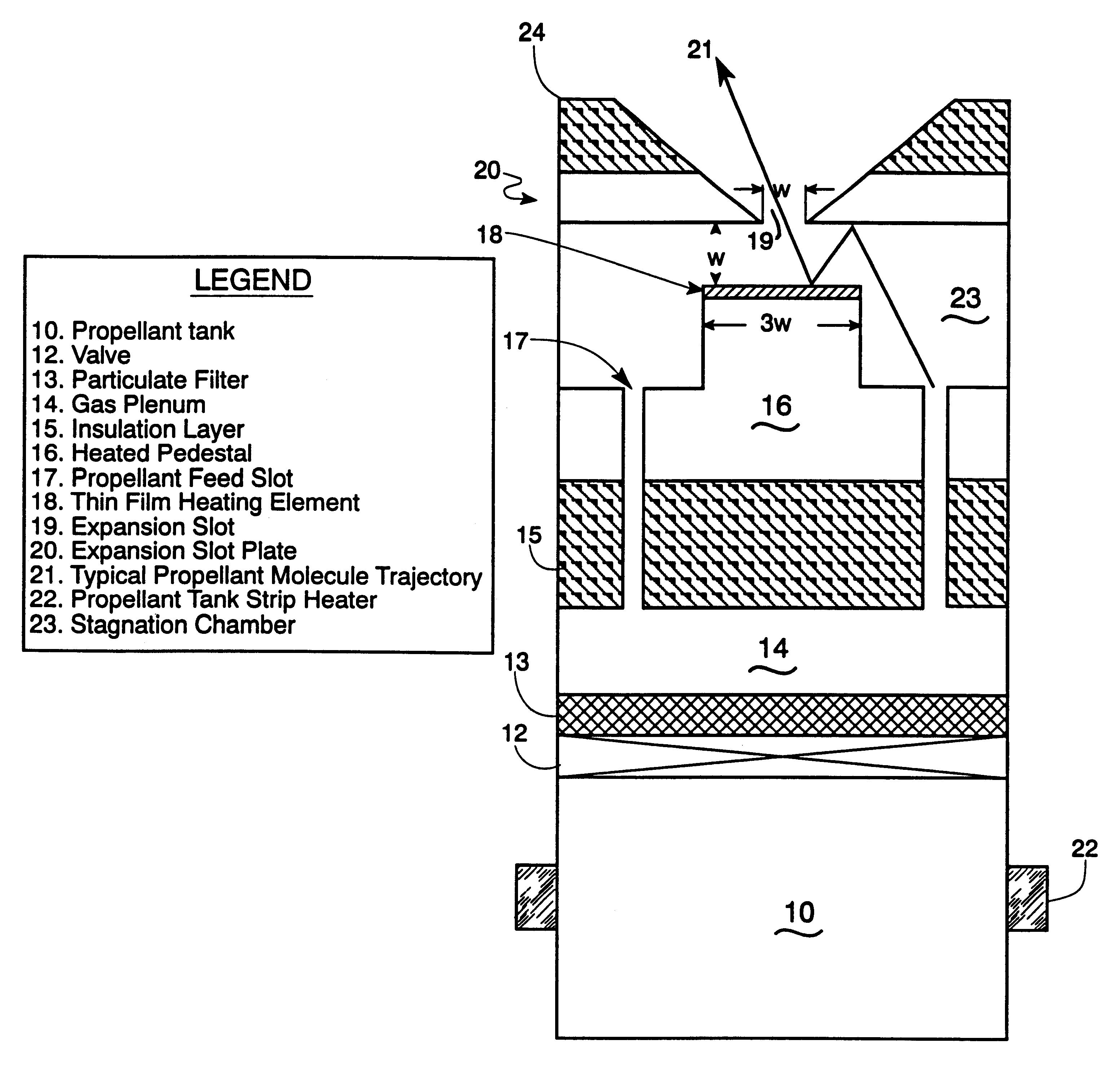
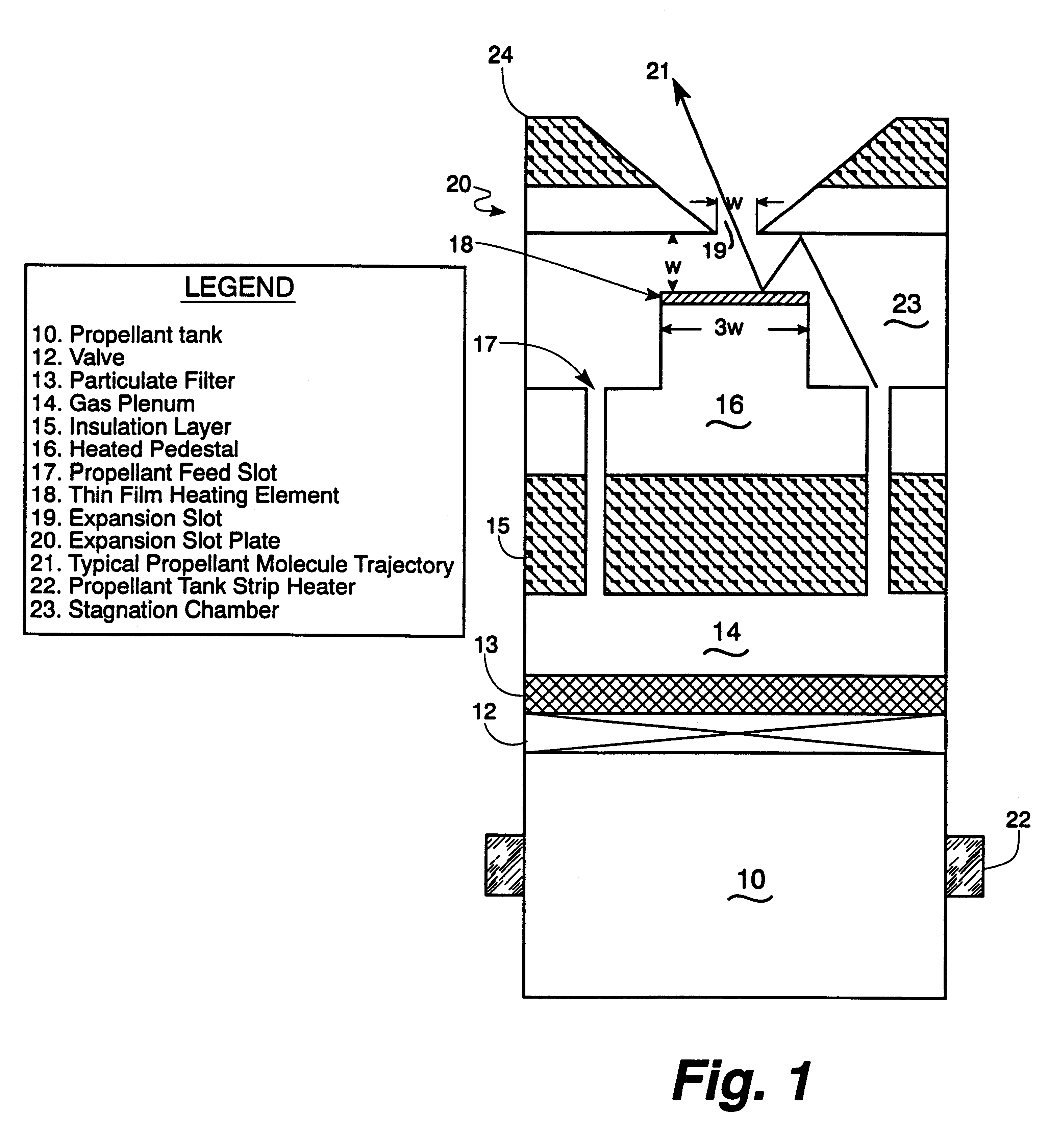
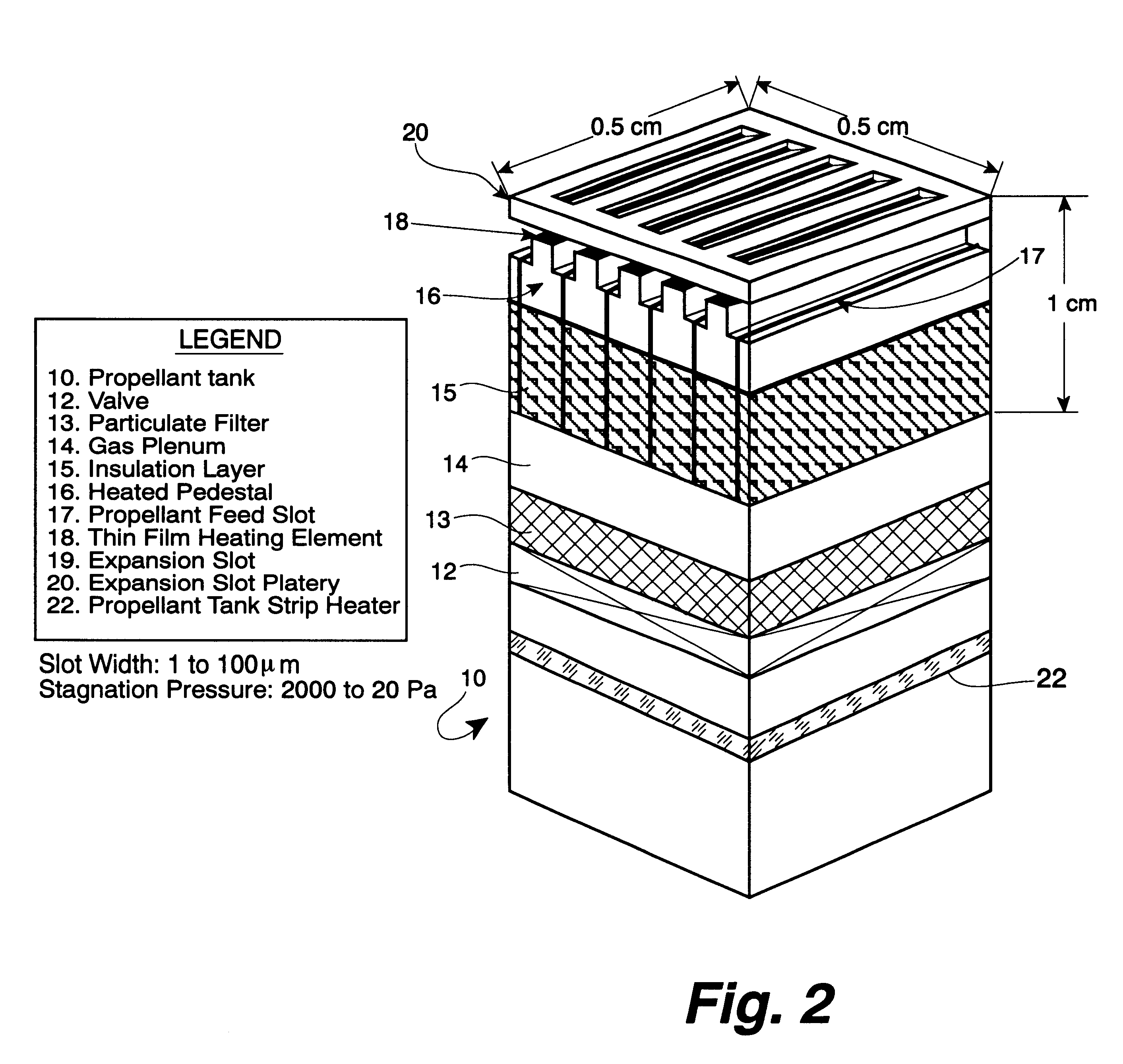
Referring in more detail of the drawings, the compact thruster of the invention operates as follows per FIGS. 1 and 2. Propellant, in liquid or solid form, is stored in a propellant tank 10. When the thruster is to be operated, the valve 12 is opened and gaseous propellant flows through a filter 13 to remove any large particulates into a gas plenum 14. The operating pressure for the thruster is regulated by heating the propellant storage tank with a small heater 22 and operating at the appropriate vapor pressure for the propellant of choice (typically ammonia or water). The plenum feeds gaseous propellant into the stagnation region 23 through several propellant feed slots 17 machined in an insulating surface 15 and the heating element pedestal plate 16. The insulating surface 15 reduces the conductive heat transfer between the heating element pedestal plate 16 and the structure below. The pedestal plate 16 is designed to reduce the line-of-sight escape of a typical propellant molecu...


PUM


Abstract

The invention provides a microthruster which includes a housing having a propellant container and a discharge section, means to heat the propellant to drive vapors toward the discharge section, a heating element to heat the vapors and one or more ports to discharge the vapors to provide thrust. Further provided is a method for powering a microthruster by flowing gas in free molecular flow therein so that a plurality of molecules of the gas contact a heating element before discharge from the microthruster.

Description

1. Field of the InventionThis invention relates to thrusters for spacecraft, particularly compact thrusters.2. Description of Related ArtMost micropropulsion systems in use today consist of cold gas thrusters which use propellants stored in gaseous form such as molecular nitrogen or helium. Gaseous propellant is stored at high pressures (10's of GPa) in volumetrically large, heavy titanium or graphite composite tanks. The propellant storage and thruster nozzle are typically separated by a complex valve system and perhaps a pressure regulator to reduce the gas pressure to the nozzle. Because the propellant is stored at very high pressures, the valve is typically very large in size to reduce valve leakage. These valves also typically require several Watts of power to actuate. The nozzle throat diameter for a cold gas thruster for a microsatellite mission can be on the order of 10 .mu.m. This makes the cold gas thruster susceptible to particulate contamination plugging of the nozzle. F...

Claims


Application Information

Patent Timeline
Patent Type & Authority Patents(United States)
IPC IPC(8): B64G1/22B64G1/40F02K9/00F02K9/68F02K9/94F03H1/00B64G1/24B64G1/26B81B1/00
CPCF02K9/94F02K9/68B64G1/406B64G1/26B64G1/415
Inventor KETSDEVER, ANDREW D.MUNTZ, ERIC P.
Owner THE GOVERNMENT OF THE US SEC THE AIR FORCE
Why Eureka
Try Eureka