
Fuel injection valve for internal combustion engines

a technology for internal combustion engines and fuel injection valves, which is applied in the direction of fuel injection apparatus, machine/engines, feed systems, etc., can solve the problems of large installation space, large size, and high cost of manufacturing known fuel injection valves, and achieve the effect of preventing damage to the sealing seat, reducing installation space, and reducing installation spa

Inactive Publication Date: 2001-08-07
ROBERT BOSCH GMBH
View PDF9 Cites 12 Cited by
  • Summary
  • Abstract
  • Description
  • Claims
  • Application Information

AI Technical Summary

Benefits of technology

The fuel injection valve for internal combustion engines according to the invention, has the advantage over the prior art that the spring chamber itself is utilized as a hydraulic damper. This becomes possible in a structurally simple way as a result of not draining the leaking oil quantity out of the spring chamber; as a result, the fuel-filled pressure chamber acts as a hydraulic work chamber, which brings an additional closing force to bear on the valve member. The hydraulic closing force of the damping chamber has a variable effect depending on the engine operating state, that is, the rpm, load and temperature. The degree of damping or the closing force can be adjusted by way of the play between the valve member and the guide bore wall guiding the valve member, and by way of the size of the damping volume of the spring chamber. Along with shaping the opening course, the closing stroke motion of the valve member can also be varied; the closing pressure in the spring chamber, which rises as the load and rpm rise, also brings about faster closure of the valve member at the end of injection. This kind of fast closure of the valve member prevents combustion gases from being blown back into the injection valve and thus prevents damage to the sealing seat.The load- and rpm-dependent hydraulic closing pressure in the spring chamber thus makes a low opening pressure of the fuel injection valve possible; along with the damping of the valve member stroke, the result is that the ignition lag during injection in the engine is shortened, which thus lessens the noise of combustion. When the still-cold engine is started, this effect of the valve member stroke damping is amplified by the viscosity of the fuel, which thus compensates for the increased combustion noise of the Diesel engine in this operating state. The highest closing pressure in the spring chamber prevails when the rated rpm range is reached, and then the fast closure of the valve member prevents combustion gases from being blown back.With the fuel injection valve of the invention, it is thus possible in a structurally simple way to perform a shaping of the injection course at the fuel injection valve for the sake of noise abatement.Further advantages and advantageous features of the subject of the invention can be learned from the specification, the drawing and the claims.

Problems solved by technology

The known fuel injection valve has the disadvantage, however, that because it requires two valve springs and the additional damping chamber, it is very large in size and takes up a large amount of installation space, which is often unavailable in modern internal combustion engines.
Moreover, manufacturing the known fuel injection valve is relatively complicated and thus expensive.

Method used


Image

  • Fuel injection valve for internal combustion engines
  • Fuel injection valve for internal combustion engines

Examples


Embodiment Construction

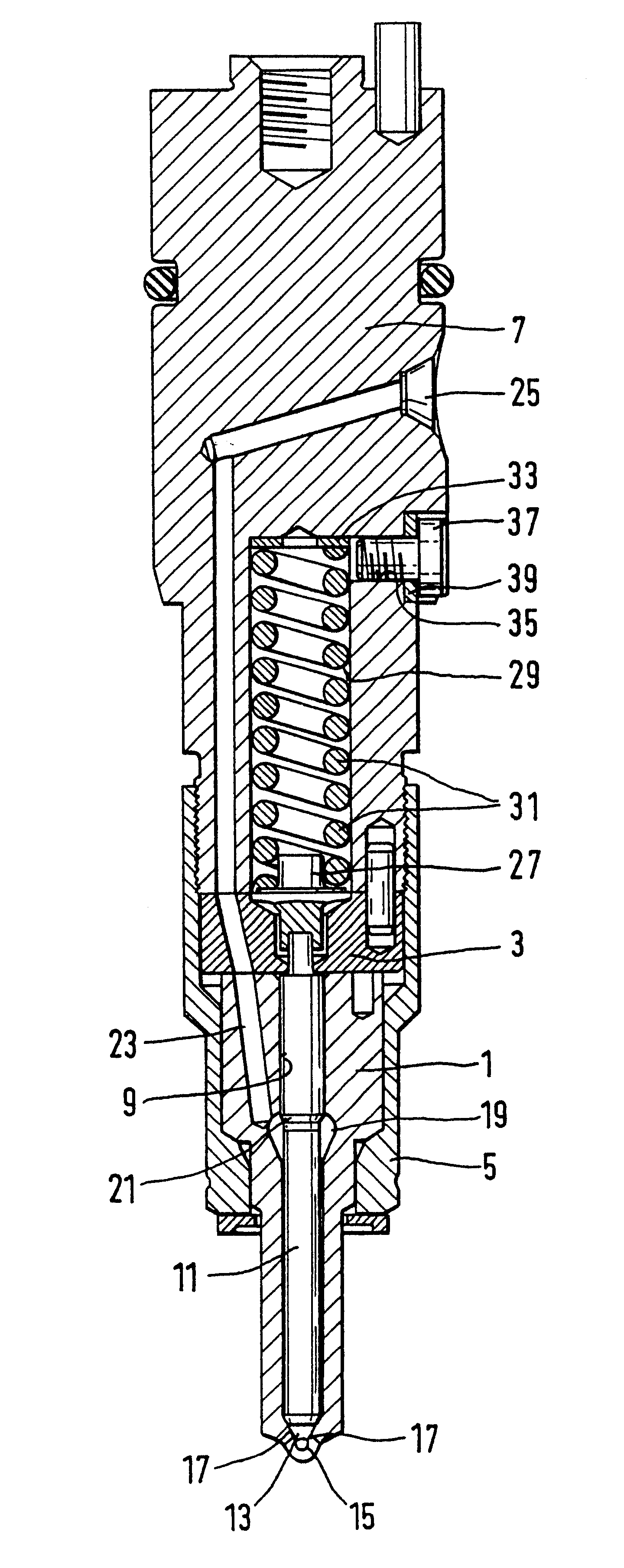
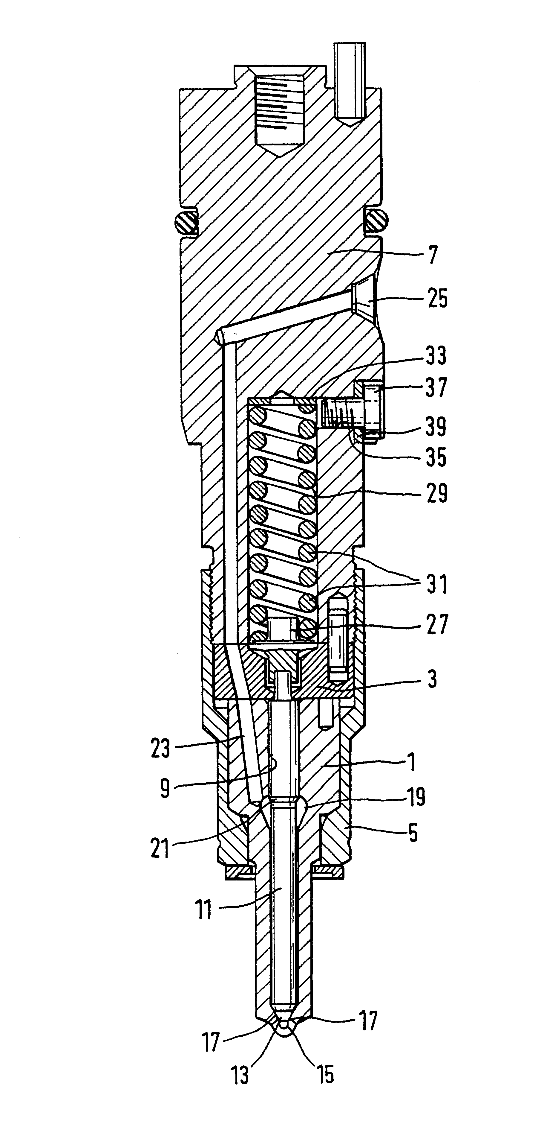
The fuel injection valve for internal combustion engines shown in FIG. 1 has a valve body 1, which together with a shim 3 that contacts its face end remote from the combustion chamber is firmly fastened on a valve holding body 7 by means of a union nut 5. The valve body 1, protruding with its end remote from the shim 3 into a combustion chamber, not shown, of an internal combustion engine has a guide bore 9, in which a piston-like valve member 11 is axially displaceably guided; on one face end, the valve member has a conical sealing face 13, with which it cooperates with a valve seat 15 formed by a reduction in the diameter of the guide bore 9. This valve seat 15 is disposed on the closed end toward the combustion chamber of the valve body 1 and borders on injection openings 17, provided on the end of the guide bore 9, which adjoin the valve seat 15 downstream in the injection direction. The guide bore 9 of the valve member 11 is widened at one point to form a pressure chamber 19, i...


PUM


Abstract

A fuel injection valve for internal combustion engines, having a valve member that is axially displaceable in a valve body and that with a sealing face cooperates, to control an injection opening, with a valve seat face on the valve body. An end of the valve member remote from the combustion chamber is urged in the closing direction by a valve spring disposed in a spring chamber. The valve member has a pressure shoulder acting in the opening direction, which protrudes into a pressure chamber that is filled with high fuel pressure. Via a throttle gap, the spring chamber communicates with the pressure chamber and is sealed off from a fuel return system, so that during the opening stroke motion of the valve member the spring chamber acts as a hydraulic damper.

Description

PRIOR ARTThe invention is based on a fuel injection valve for internal combustion engines. In one such fuel injection valve, known from German patent disclosure DE 44 40 182 A1, a piston-like valve member is axially displaceably guided in a guide bore of a valve body. The valve body has a sealing face on its end toward the combustion chamber, and with this face the valve body cooperates with a valve seat face disposed on the valve body, in order to control an injection opening. With its end remote from the combustion chamber, the valve member protrudes into a spring chamber, in which at least one valve spring is disposed that urges the valve member in the closing direction toward the valve seat face. The valve member also has a pressure shoulder, which protrudes into a pressure chamber that can be filled with high fuel pressure, and this shoulder is embodied such that the high fuel pressure engaging the pressure shoulder urges the valve member in the opening direction, counter to th...

Claims


Application Information

Patent Timeline
Patent Type & Authority Patents(United States)
IPC IPC(8): F02M61/20F02M61/00F02M45/12F02M45/00F02M63/00F02M61/10F02M45/08
CPCF02M45/12F02M61/205F02M2200/304
Inventor RIPPER, WOLFGANGWAGNER, WERNERDITTUS, BERNDMACK, MANFRED
Owner ROBERT BOSCH GMBH
Learn More