Vibration motor holding apparatus and portable electronic equipment having the same

a technology of vibration motor and holding apparatus, which is applied in the direction of mechanical vibration separation, instruments, casings/cabinets/drawers details, etc., can solve the problems of increasing labor-hour and cost, unable to extract vibration motor by automatic sucking machine, and inability to perform ceiling sucking

Inactive Publication Date: 2001-08-14
PANASONIC CORP
View PDF4 Cites 52 Cited by
  • Summary
  • Abstract
  • Description
  • Claims
  • Application Information

AI Technical Summary

Problems solved by technology

In that case, first, the vibration motor cannot be extracted by the automatic sucking machine if the vibration motor has a shape similar to that as mentioned above.
However, the aforementioned vibration motor is not even in the ceiling of the vibration motor because a sintered oilless bearing for rotatably supporting a shaft lies at the center of a cover.
Therefore, even if the ceiling is sucked pneumatically by the automatic sucking machine, the air leaks from a gap between the shaft and the bearing so that sucking of the ceiling cannot be performed.
Further, since the vibration motor in the conventional art is not designed to suit a refl...

Method used


Image

  • Vibration motor holding apparatus and portable electronic equipment having the same
  • Vibration motor holding apparatus and portable electronic equipment having the same
  • Vibration motor holding apparatus and portable electronic equipment having the same

Examples


Embodiment Construction

The present invention will be described in detail with reference to the accompanying drawings.

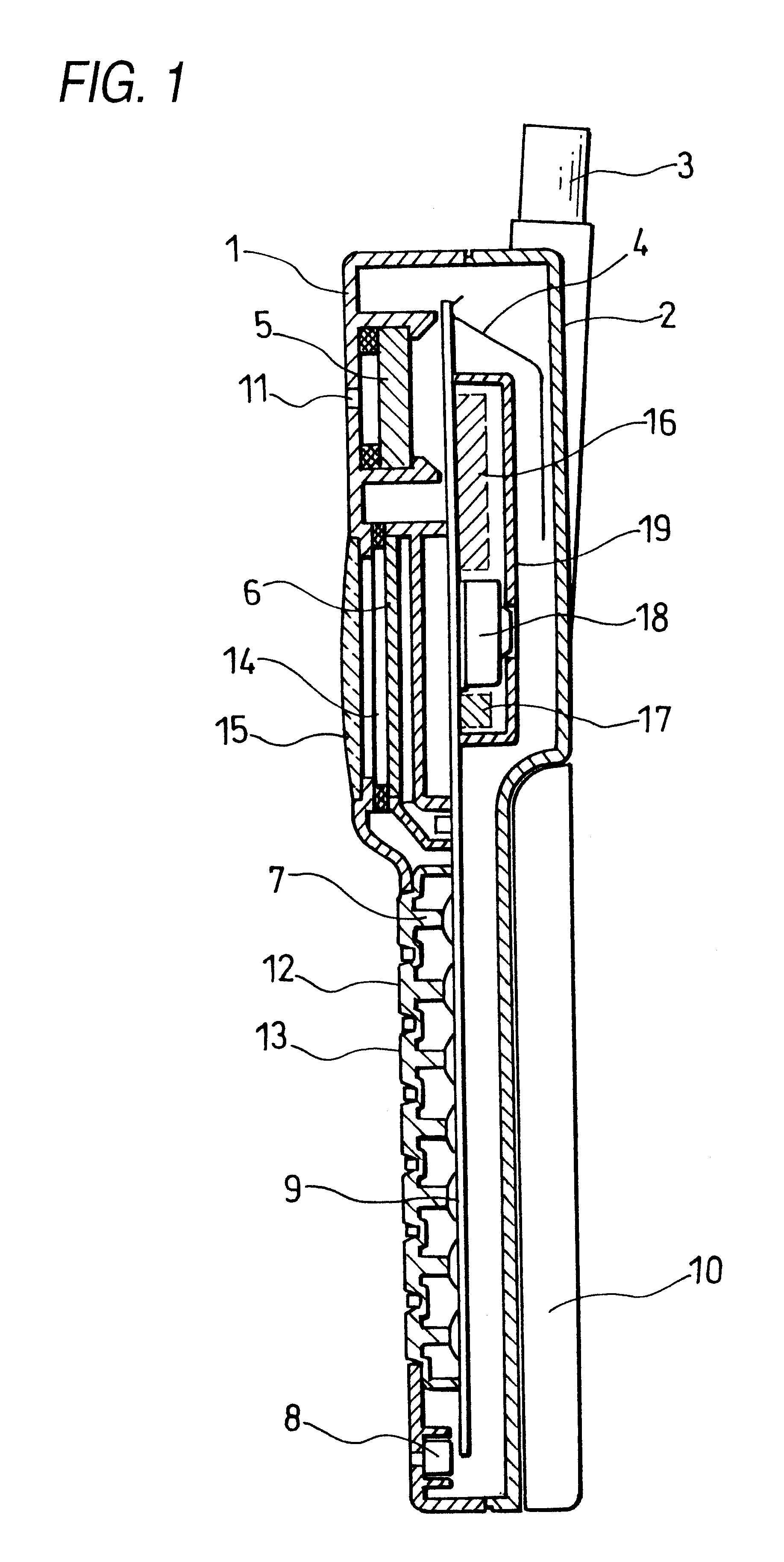
FIG. 1 is a sectional view of a portable electronic equipment having a vibration motor holding apparatus according to an embodiment of the present invention.

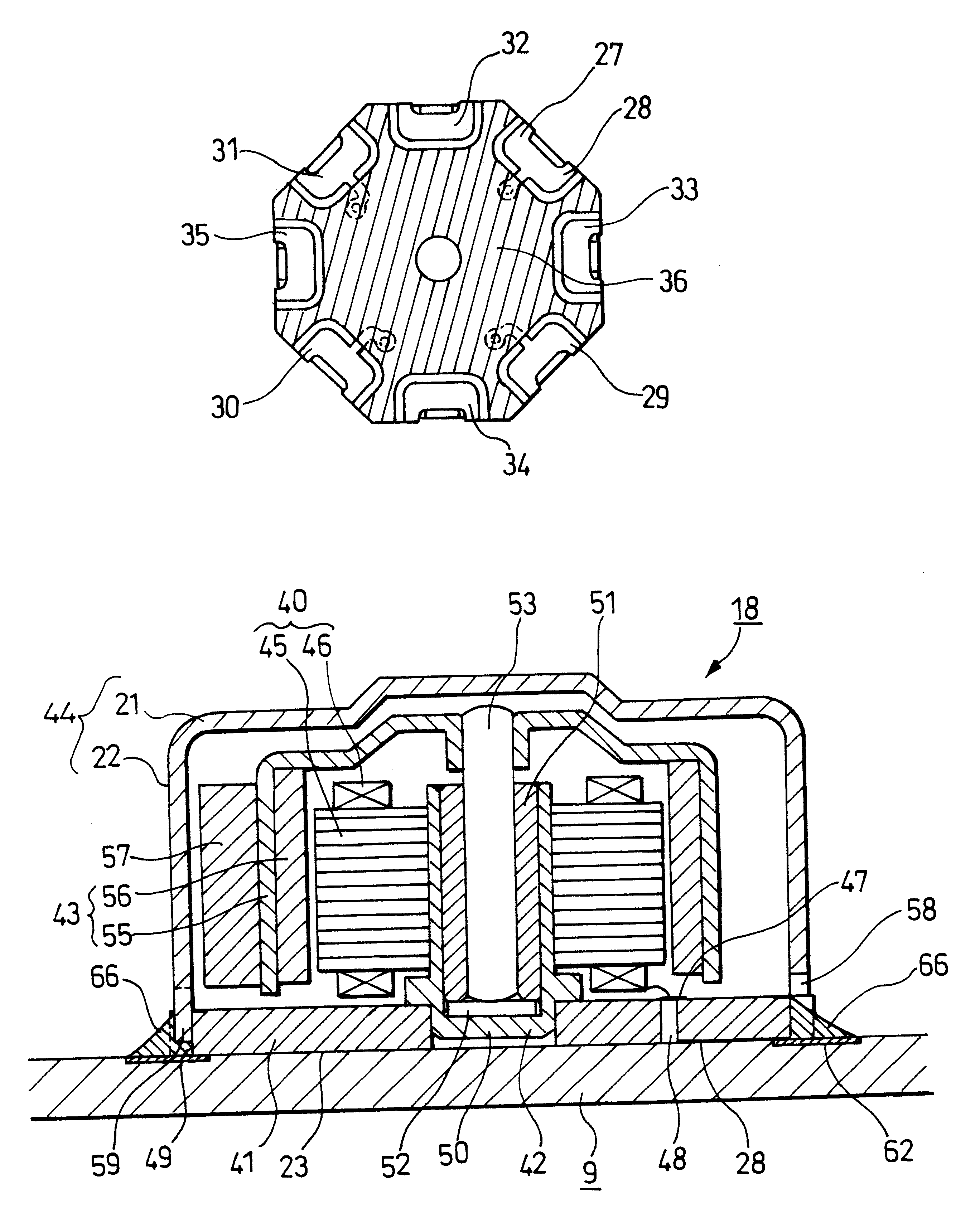
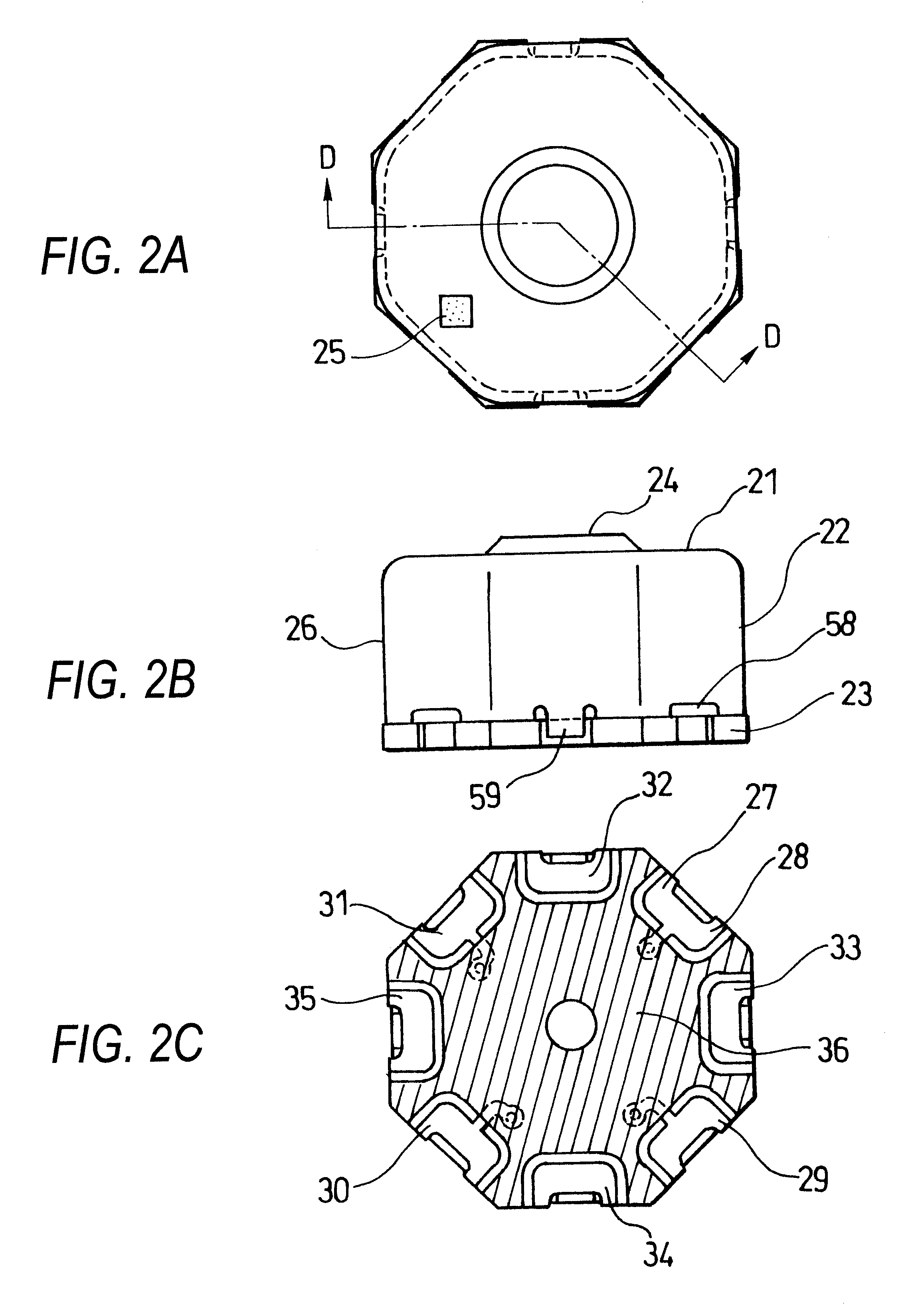
FIGS. 2A to 2C are views each showing a configuration of a motor shown in FIG. 1.

FIG. 3 is a sectional view when the motor shown in FIGS. 2A to 2C is mounted on a main-body printed board.

FIG. 4 is an exploded perspective view of the main-body printed board, the motor and a shield case shown in FIG. 3.

FIG. 5 is a view showing a state in which the motor is mounted on the main-body printed board shown in FIG. 4.

In FIG. 1, a transmitting / receiving antenna 3, a receiving antenna 4, a receiver 5 for outputting voice, a liquid-crystal display 6 for displaying characters, symbols and so on, a key sheet 7 on which characters / symbols are printed, a transmitter 8, a main-body printed board 9 and so on are disposed in a case formed by an upper case...


PUM


Abstract

A vibration motor 18 constituted by a motor provided with a weight 57 is covered with a cover 44 having a flat portion for making the cover 44 be sucked easily and a marking for positioning, and this vibration motor is mounted on a main-body printed board 9. In this main-body printed board, line lands and main-body lands also having a function for identification are provided outside the outline of the mounted vibration motor, so that a displacement of the mounting position can be easily detected even visually.

Description

1. Technical Field of the InventionThe present invention relates to a vibration motor which is used in a portable electronic equipment such as a portable telephone, a pocket bell or the like, and which silently informs a user of incoming etc. by vibration, and relates to a portable electronic equipment having the vibration motor.2. Description of the Related ArtJP-A-10-248203 discloses one of conventional vibration motors used as silent information sources in miniature radio communication equipment, in which a cored-type brushless vibration motor is disclosed.FIG. 6 is a sectional view of a main portion of the cored-type brushless vibration motor.In FIG. 6, a bearing holder portion 102 is provided at the center of a bracket 101 forming the bottom of the vibration motor. This bearing holder portion 102 has a catch portion 103 and an erected portion 104 formed by cutting and erecting a part of the bracket 101.A sintered oilloss bearing 105 is attached to the inside of this bearing hol...

Claims


Application Information

Patent Timeline
IPC IPC(8): B06B1/02B06B1/04H02K7/06H05K1/02H05K3/30G10K9/12H02K5/00H02K7/065H02K29/00H04M1/02H05K1/18H05K5/02
CPCB06B1/04G10K9/13H02K7/063H05K1/0269H05K2203/166H05K3/303H05K2201/09781H05K2201/10371
Inventor SATOH, NORIYOSHIHIRAI, KOUTAROU
Owner PANASONIC CORP
Why Eureka
Try Eureka