Termination of transmission lines using simultaneously enabled pull-up and pull-down circuits

a technology of transmission lines and pull-down circuits, applied in the direction of pulse techniques, instruments, and increasing reliability, can solve problems such as limiting the performance of the overall system

Inactive Publication Date: 2001-08-14
SUN MICROSYSTEMS INC
View PDF21 Cites 24 Cited by
  • Summary
  • Abstract
  • Description
  • Claims
  • Application Information

AI Technical Summary

Problems solved by technology

The signal frequency at which this communication ...

Method used


Image

  • Termination of transmission lines using simultaneously enabled pull-up and pull-down circuits
  • Termination of transmission lines using simultaneously enabled pull-up and pull-down circuits
  • Termination of transmission lines using simultaneously enabled pull-up and pull-down circuits

Examples


Embodiment Construction

Those of ordinary skill in the art will realize that the following description of the present invention is illustrative only and not in any way limiting. Other embodiments of the invention will readily suggest themselves to such skilled persons having the benefit of this disclosure.

The use of the same reference symbols in different figures indicates similar or identical items.

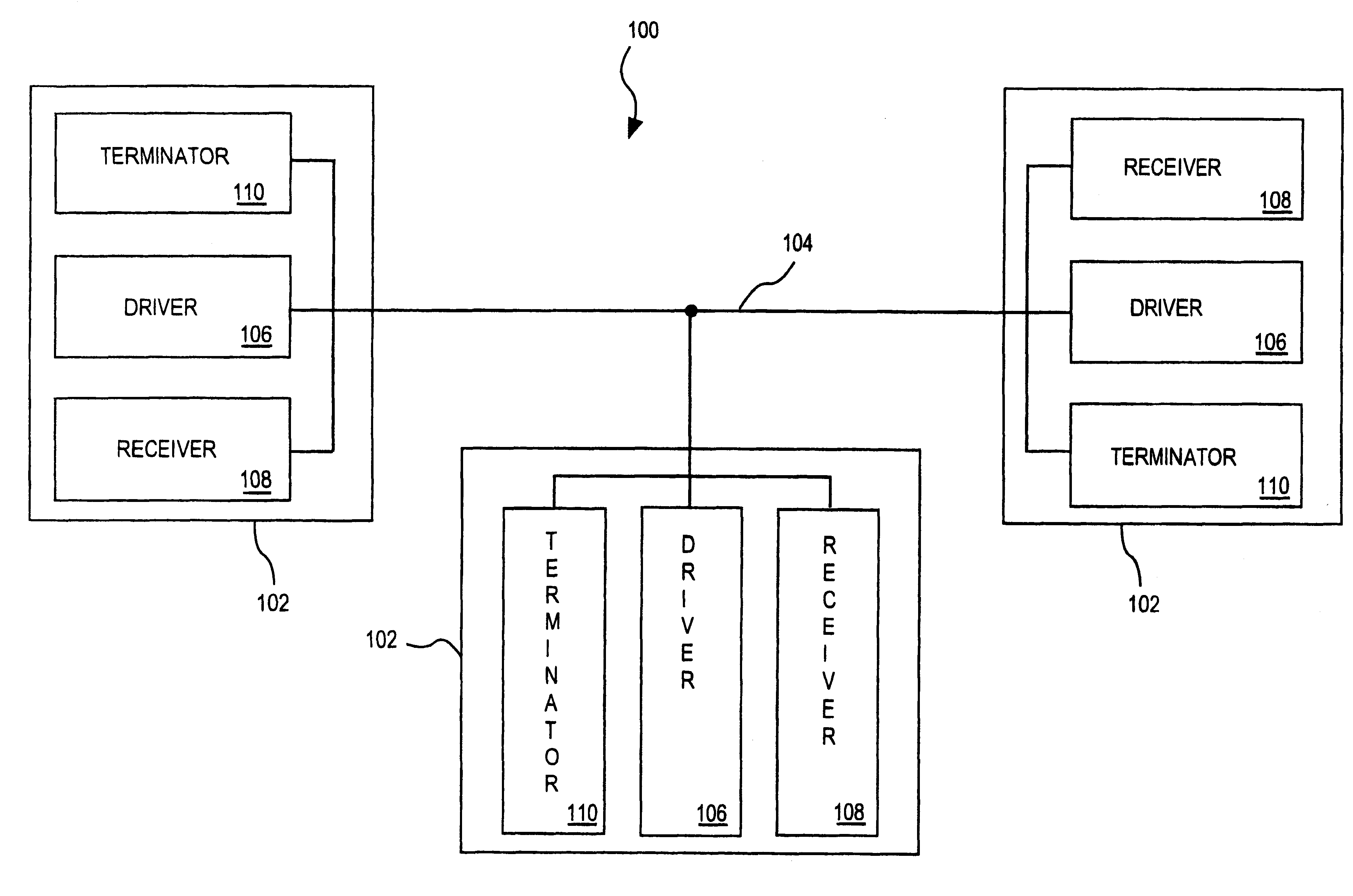
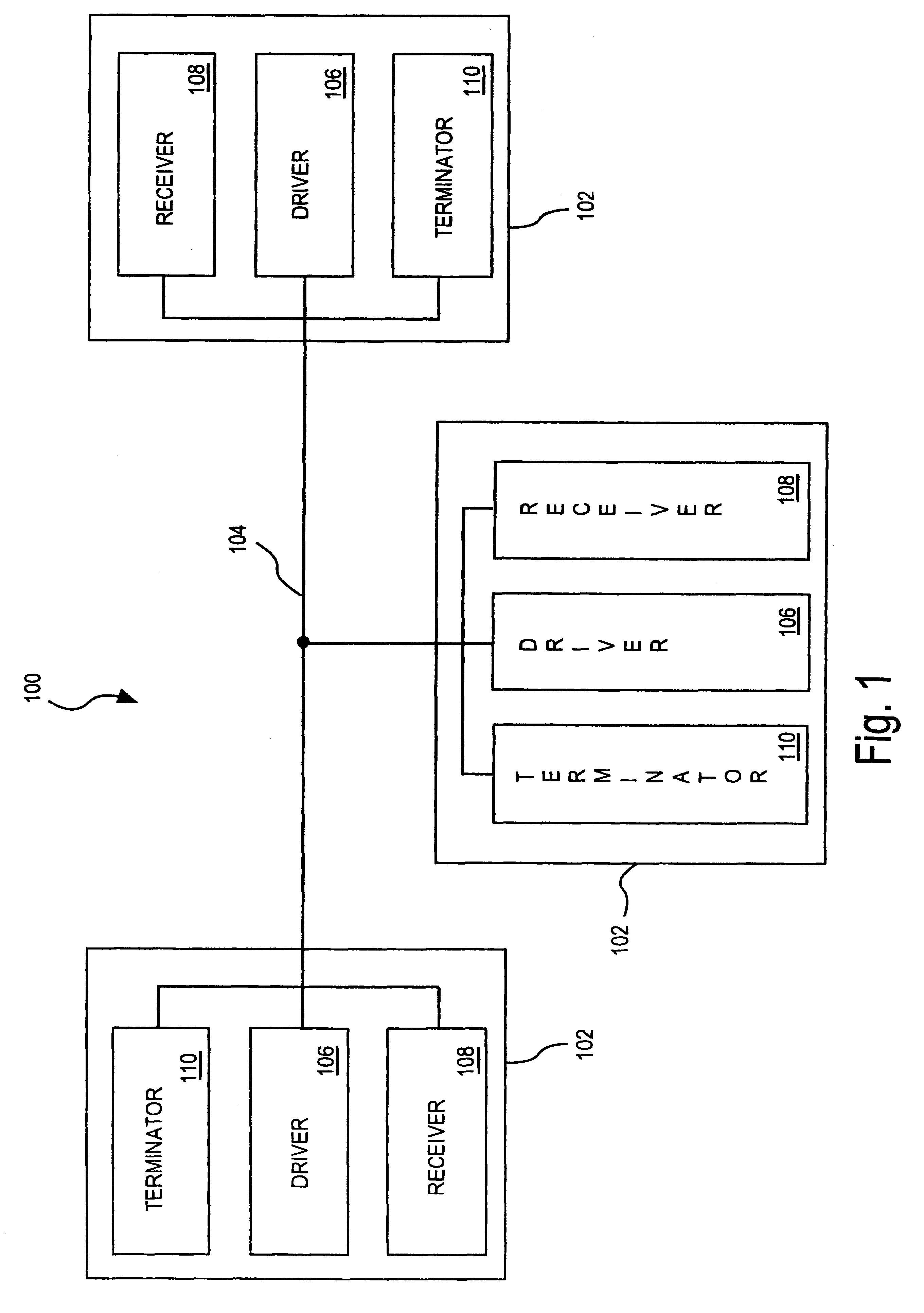
FIG. 1 is a block diagram of an information handling system having driver, receiver, and termination circuits in accordance with the present invention.

Referring to FIG. 1, information handling system 100 includes a plurality of devices 102 which communicate with each other over transmission lines 104.

Each component 102 includes a driver circuit 106, a receiver circuit 108 and an optional terminator circuit 110. The output resistance of each of driver circuits 106 is controlled using impedance control circuitry as is known in the art. One such means of controlling the output resistance of a driver is disclosed i...


PUM


Abstract

An information handling system includes a plurality of transmission lines coupled together at one end and having a characteristic impedance, a driver circuit coupled to one of the transmission lines, and at least one receiver circuit coupled to the transmission lines. At least one driver circuit includes pull-up and pull-down circuits each having output resistances. The parallel combination of the pull-up and pull-down resistances matches the characteristic impedance of the transmission line. When the driver is used to terminate the transmission line, the pull-up and pull down circuits are enabled at approximately the same time, thus terminating the line. On-chip terminators may alternatively be used for termination, the terminators either including pull-up and pull-down circuits substantially similar to those described for the drivers, or may include a single resistance tied to a voltage other than an upper or lower rail. A method for managing the information handling system described above includes terminating each node by causing either an on-chip terminator or a driver to go into a terminating mode, thus causing the termination of the line using an output resistance that matches the characteristic impedance of the transmission line.

Description

1. Field of the InventionThe present invention relates to buses and more particularly to termination of buses for use in information processing systems.2. Description of the Related ArtIn computer and information processing systems, various integrated circuit chips communicate digitally with each other over a common bus. The signal frequency at which this communication occurs can limit the performance of the overall system. Thus, the higher the communication frequency, the better. The maximum frequency at which a system communicates is a function not only of the time that it takes for the electromagnetic wavefronts to propagate on the bus from one chip to another, but also of the time required for the signals to settle to levels that can be recognized reliably at the receiving bus nodes as being high or low, referred to as the settling time.The length of the settling time is a function of the amount of reflection and ringing that occurs on the transmission line. The more effective t...

Claims


Application Information

Patent Timeline
IPC IPC(8): G06F13/40
CPCG06F13/4086
Inventor STARR, JONATHAN E.
Owner SUN MICROSYSTEMS INC
Why Eureka
Try Eureka