Gas powered gun and assemblies therefor

a gas-powered gun and gas-powered technology, applied in the field of guns, can solve the problems of affecting the performance of guns using conventional regulators

Inactive Publication Date: 2001-08-21
DILLON JOSEPH
View PDF10 Cites 64 Cited by
  • Summary
  • Abstract
  • Description
  • Claims
  • Application Information

AI Technical Summary

Problems solved by technology

Such guns using conventional regulators have a natural tendency to freeze due to the inherent frigid characteristics of liquid gases used in the canisters.
Whether using CO.sub.2 or similar gasses, which frost immediately upon pressure decrease, or just compressed air, the regulators on prior art tend to freeze when highly compressed air from a canister is regulated down to a useable pressure for the gun.
Consequently gun performance can be severely inhibited when rapid fire of the gun causes repeated and increased cooling of the regulator which must lower the pressure supplied to fire the projectile when the trigger is activated.
Further, the regulators used currently, also tend to leave compressed air in the gun sufficient to power one more projectile down the barrel, even after the canister is removed from communication with the input side of the regulator.
The result being a very dangerous situation wherein the gun appears to be safe with the air canister removed, while in fact, one more shot is possible if the trigger is pulled.
A second problem with current art in the field of air powered guns and more specifically paint ball guns, is the complexity of the trigger mechanisms.
The complex systems of cams, rods, springs, and hooks, currently in

Method used


Image

  • Gas powered gun and assemblies therefor
  • Gas powered gun and assemblies therefor
  • Gas powered gun and assemblies therefor

Examples


Embodiment Construction

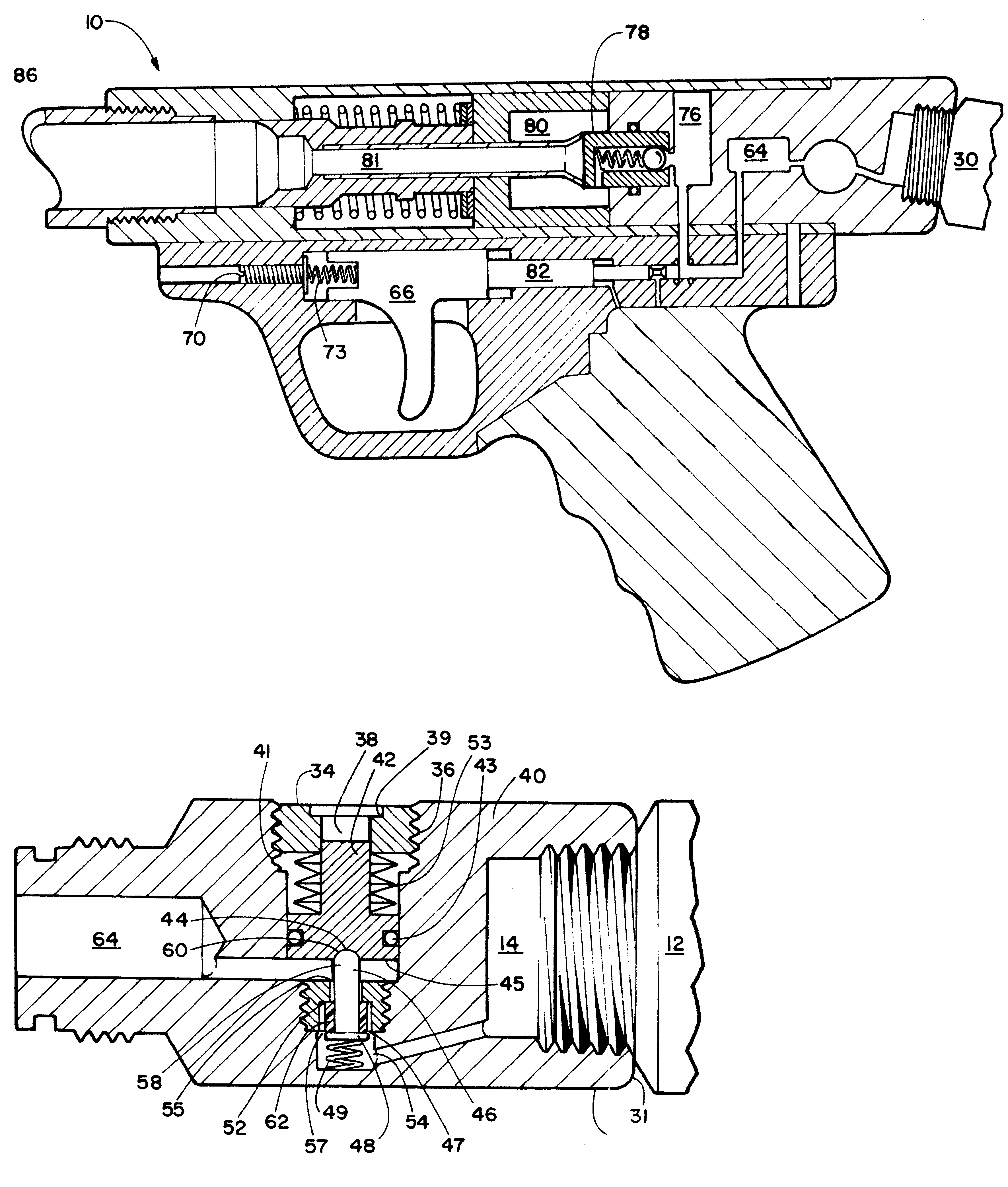
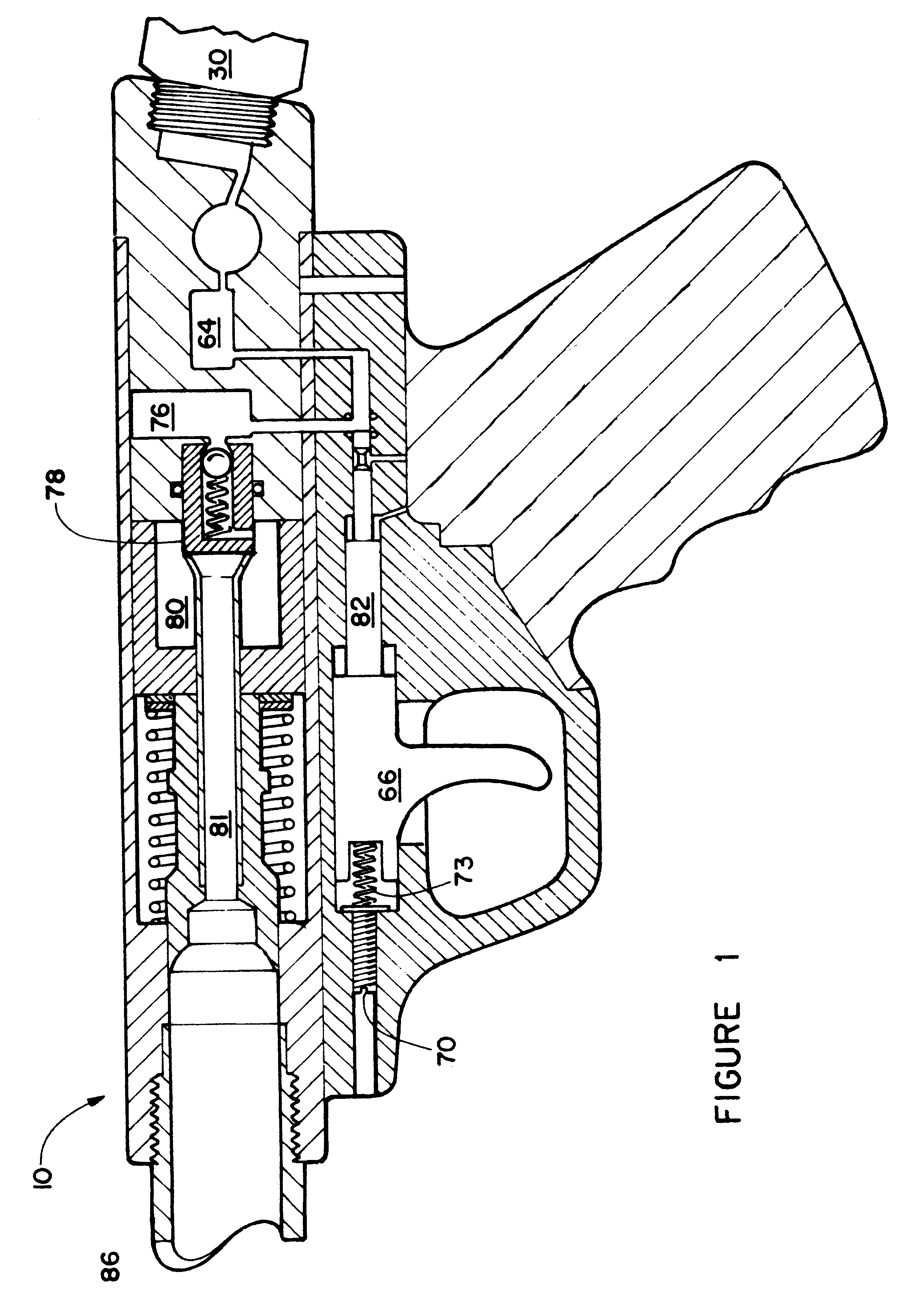
Referring now to the drawing figures which depict the preferred embodiments of the invention disclosed herein, specifically FIG. 1 is a cut away side view of an improved air gun 10 showing having a regulator means shown by the improved regulator 30 which receives highly pressurized gas from a conventional gas supply such as a pressurized canister 12 and reduces the pressure of pressurized gas received from the canister to a gas pressure desired or required to operate the gun 10.

Also shown is the air biased trigger mechanism 62 which is biased by regulated gas communicated from the regulator 30 and an adjustable rearward biasing mechanism such as a trigger spring 73 adjustable for rearward bias by trigger spring adjustment screw 79. Additional pictured is the muzzle break 70 featuring a plurality of elongated slots 72 having angled side walls 74 for better parsing of gas propellent away from any projectile being fired.

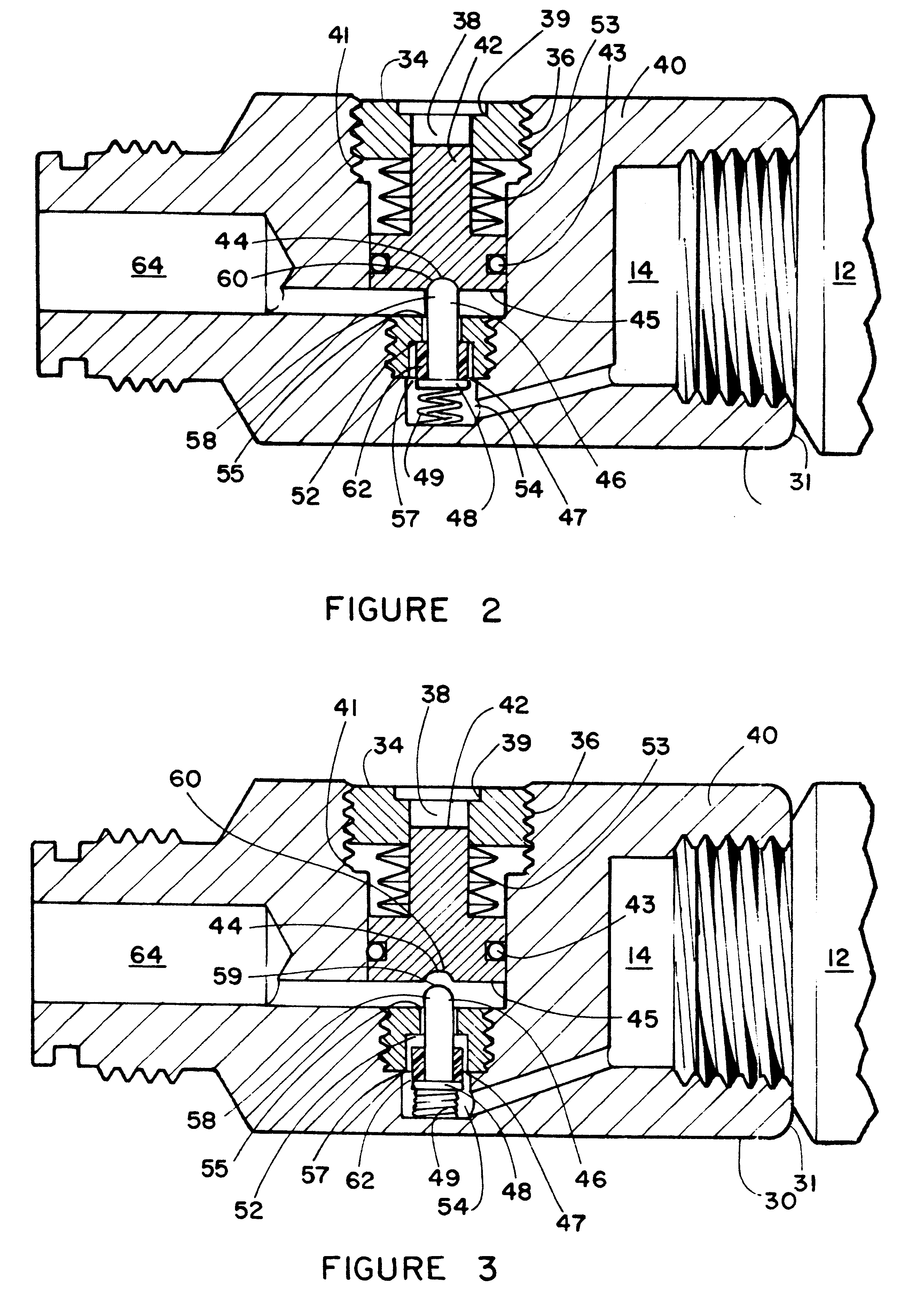
FIGS. 2 and 3 are a cut away side views of the regulator 30 in a p...


PUM


Abstract

An improved air gun for firing paint balls, pellets,, consisting of a passively venting and freeze resistant regulator, a pressure differential trigger mechanism, and a muzzle break with angled sidewalls. The freeze resistant regulator regulates incoming high pressure gas to a user predetermined pressure to operate the gun while avoiding freezing of the regulator associated with frigid incoming compressed gases and high firing rates. This is accomplished by using a heat transmission component formed by the engagement between a hemispheric shaped tip of a regulating pin and a hemispheric cavity of an adjustment piston. Passive venting of gas from the gun upon removal of the pressurized gas supply is provided by the regulator using a reciprocating regulating pin and adjustment piston which combine to compress a seal into a seat only when pressurized gas is attached to the air gun. Once detached from a pressurized air supply the compressed air in the gun vents through the seat. Firing of the gun is achieved using a pressure differential trigger mechanism capable of fine pull adjustment using a trigger biasing mechanism. Greater accuracy of projectiles leaving the gun is provided by the muzzle break featuring of a plurality of elongated oval slots having angled sidewalls to parse propulsion gases from the projectile which reduces air turbulence encountered by the projectile upon exit from the gun.

Description

1. Field of InventionThe present invention relates to guns which propel lightweight projectiles using compressed gas as a propellent. More particularly, it relates to an improved paint ball or other gas powered projectile guns such as BB or pellet guns, and a gas pressure regulator, a trigger mechanism, and a muzzle break for utilization in combination therein.2. Prior ArtCompressed air powered guns, such as paint ball guns, BB guns, and pellet guns, function to fire a projectile using compressed air as the source of power to accelerate the projectile down an axial chamber from the breech end of a gun barrel and out the muzzle or distal end of the barrel, toward the toward the target. Such air guns are conventionally powered by compressed air from a gun mounted hand activated pump for compressing air from the atmosphere into a storage chamber on the gun, or, by a canister of highly compressed gas of the user's choosing, attached to the gun, and communicating pressurized gas through ...

Claims


Application Information

Patent Timeline
IPC IPC(8): F41B11/00F41B11/32
CPCF41B11/723F41B11/724
Inventor DILLON, JOSEPH
Owner DILLON JOSEPH
Why Eureka
Try Eureka