Filter with stiffening ribs

a filter and rib technology, applied in the field of filters, can solve the problems of passenger injuries, bag integrity damage, airbag failure, etc., and achieve the effects of improving hoop strength, and reducing the risk of injury

Inactive Publication Date: 2001-08-21
ACS TECH
View PDF24 Cites 30 Cited by
  • Summary
  • Abstract
  • Description
  • Claims
  • Application Information

AI Technical Summary

Benefits of technology

Another object of this invention is to provide a simple airbag filter that has reinforcement to better withstand the explosive force of the gas generation.
Still another object of this invention is to provide a light-weight, inexpensive, and effective filter device for airbags.
These and other objects of the invention are achieved in one aspect by a wire mesh filter deformed to create a plurality of ribs around the circumference of the filter. The filter can be deformed by being pressed into a mold. The circumference of ribs provides an improved hoop strength for the filter.

Problems solved by technology

Much of this matter is not only extremely hot but also of a caustic composition, and the particulate matter, travelling a high velocity, is potentially dangerous to the integrity of the bag and the occupant to be protected thereby.
If no measures are taken to ameliorate the degradative effects of this mixed phase reaction mixture, the gases and / or particulates would penetrate the bag, likely causing its failure and, in the most serious situations, causing injuries to the passenger.
There are other trade-offs, as particulate deflection devices are typically expensive machined parts which are fabricated from heavy steel plate (because they are not amenable to fabrication by stamping, their cost of manufacturing is increased).
According to the above-referenced '323 patent, there is also a problem with quality control in the mass fabrication of such screen-mat composites with respect to providing a uniform pressure drop across any given filter made.
Yet another problem in designing airbag filter devices is that as the filter becomes clogged, the pressure drop across the filter increases.
That is, if the filter is made of very fine wire mesh or wool to assure catching all of the molten slag particles, then the mesh or wool fibers will have insufficient mass to cool the impinged slag particle to a solid, and so the molten slag particle melts through the mesh or wool and / or it fragments into smaller particles that may eventually pass through the filter and impinge the airbag.
Moreover, these newer generation gas generators still yield a significant explosive force against which the filter element must be stabilized.

Method used


Image

  • Filter with stiffening ribs
  • Filter with stiffening ribs
  • Filter with stiffening ribs

Examples


Embodiment Construction

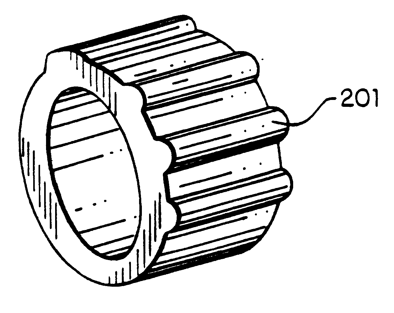
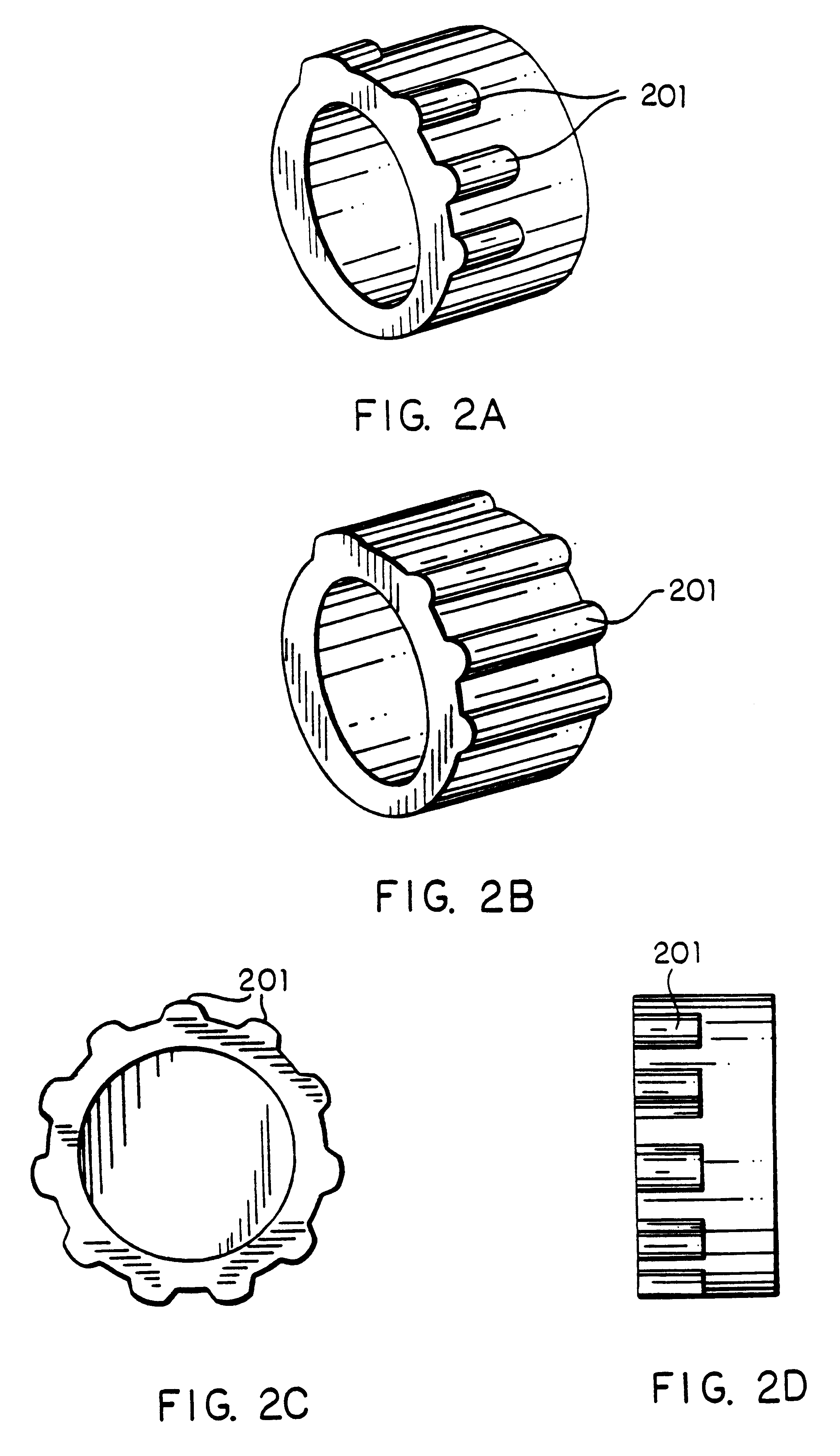
In brief, wire of a particularly chosen type and diameter is knitted into a knit mesh tube having a particular width and density for the filtering application desired. A piece of the mesh tube is cut to a particular weight that is a function of the weight and filtering requirements of the environment and fluid to be filtered. The mesh tube is then pressed into the desired annular shape of a filter using a female mold, a mandrel, and a plunger or press to produce a filter having the desired physical dimensions, weight, and density. The annular filter is then further shaped in a mold to deform the outer annular circumference into a series of ribs.

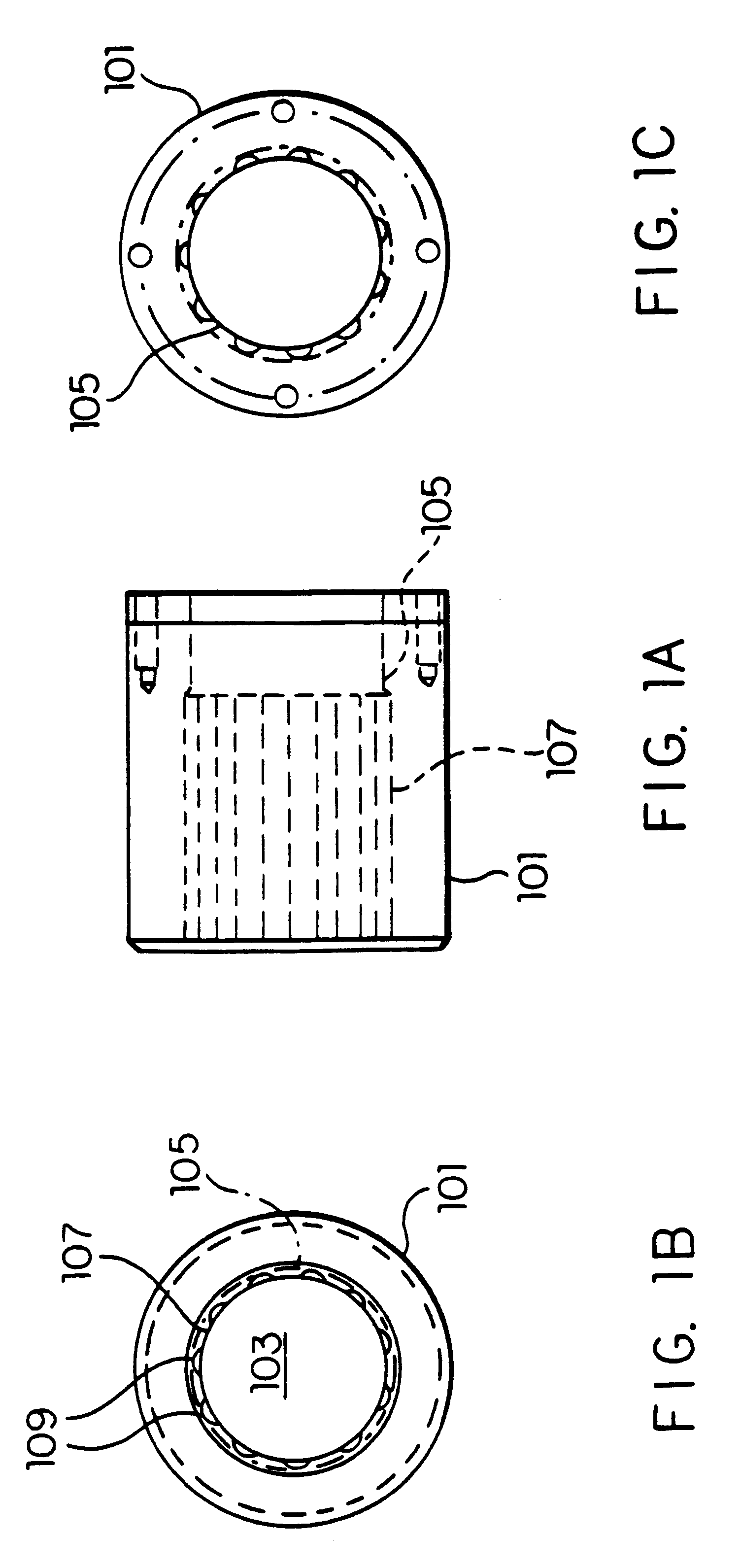
Shown in FIG. 1 (left to right) are a top, side, and bottom view of the mold 101 used to form the ribs on the mesh filter. The mold is preferably made of a hard tool steel. The mold has an internal cavity 103 defined by an inner annular circumference. The tool shown in FIG. 2 is used to make a filter having ribs as shown in FIGS. 2A and 2D, i...


PUM

PropertyMeasurementUnit
diameteraaaaaaaaaa
lengthaaaaaaaaaa
lengthaaaaaaaaaa

Abstract

Annular wire mesh filters for airbag assemblies for passenger vehicles are provided with a series of ribs extending parallel with the axis of the annulus and along the outer wall. The ribs provide added strength to the filter. Also provided is a method of manufacturing the compressed mesh filter with a uniform density, and a molding tool (mold, mandrel, and plunger) for making the compressed mesh articles of this invention.

Description

1. The Field of the InventionThis invention relates to filters, and especially filter elements useful for filtering hot gases used in the deployment of passenger airbags, and to methods for making and using such filters, and to airbags and vehicles containing the same.2. The State of the ArtRelatively recent concerns with passenger safety in land vehicles has led to the development of "airbag" technology, a passive restraint and protection system comprising a bag or pillow-like bladder that is inflated in an extremely short period of time using compressed or chemically-generated gas to fill the bag. The inflated bag is disposed or deployed between the front or side of the passenger and an interior portion of the vehicle's passenger compartment.The first generation of pyrotechnic airbag vehicle occupant restraint systems used azide compositions (typically sodium azide, NaN.sub.3, mixed a heavy metal oxide) to generate the gas used to inflate the airbag. These explosive compositions g...

Claims


Application Information

Patent Timeline
Patent Type & Authority Patents(United States)
IPC IPC(8): B01D46/10B60R21/26B60R21/261B60R21/264
CPCB01D46/10B01D2279/10B60R21/261B60R21/2644Y10T29/49604
Inventor ZETTEL, STEVEN A.SCOBORIA, RAYMOND
Owner ACS TECH
Why Eureka
Try Eureka