Thermal printer, thermal printing method and conveyor for recording material

a printing method and conveyor technology, applied in thermography, duplicating/marking methods, instruments, etc., can solve the problems of inability to reduce the size of the ink tank and the recording head of the ink jet printer, and no color printer which could be mounted in the bay of the personal computer

Inactive Publication Date: 2001-08-21
FUJIFILM CORP
View PDF13 Cites 26 Cited by
  • Summary
  • Abstract
  • Description
  • Claims
  • Application Information

AI Technical Summary

Benefits of technology

Another object of the present invention is to provide a thermal printer in which generated heat can be removed in an effective manner, and a thermal printing method and a conveyor for recording material used with the thermal printer.
Consequently structural failure in a recording material conveyor is avoided, to prevent failure in registering the three colors and irregularity in conveying the recording sheet.

Problems solved by technology

However there is no color printer which could be mounted in the bay of the personal computer, because the color printer in the prior art is too large and cannot be constructed in a small size suitable to the bay.
It is impossible to construct the printer with a thickness equal to or less than 41 mm.
There is no ink jet printer which would be mounted in the bay of the personal computer, because sizes of an ink tank and a recording head of an ink jet printer cannot be reduced and are inconsistent to the smallness of the bay.
Both the head moving mechanism and supply of ink cause problems in failure of obtaining compactness of the body.
However there is no known color thermal printer which would be mounted in the bay of the personal computer, because of considerable largeness of parts and components in a color thermal printer and a large space required for their arrangement.

Method used


Image

  • Thermal printer, thermal printing method and conveyor for recording material
  • Thermal printer, thermal printing method and conveyor for recording material
  • Thermal printer, thermal printing method and conveyor for recording material

Examples


Embodiment Construction

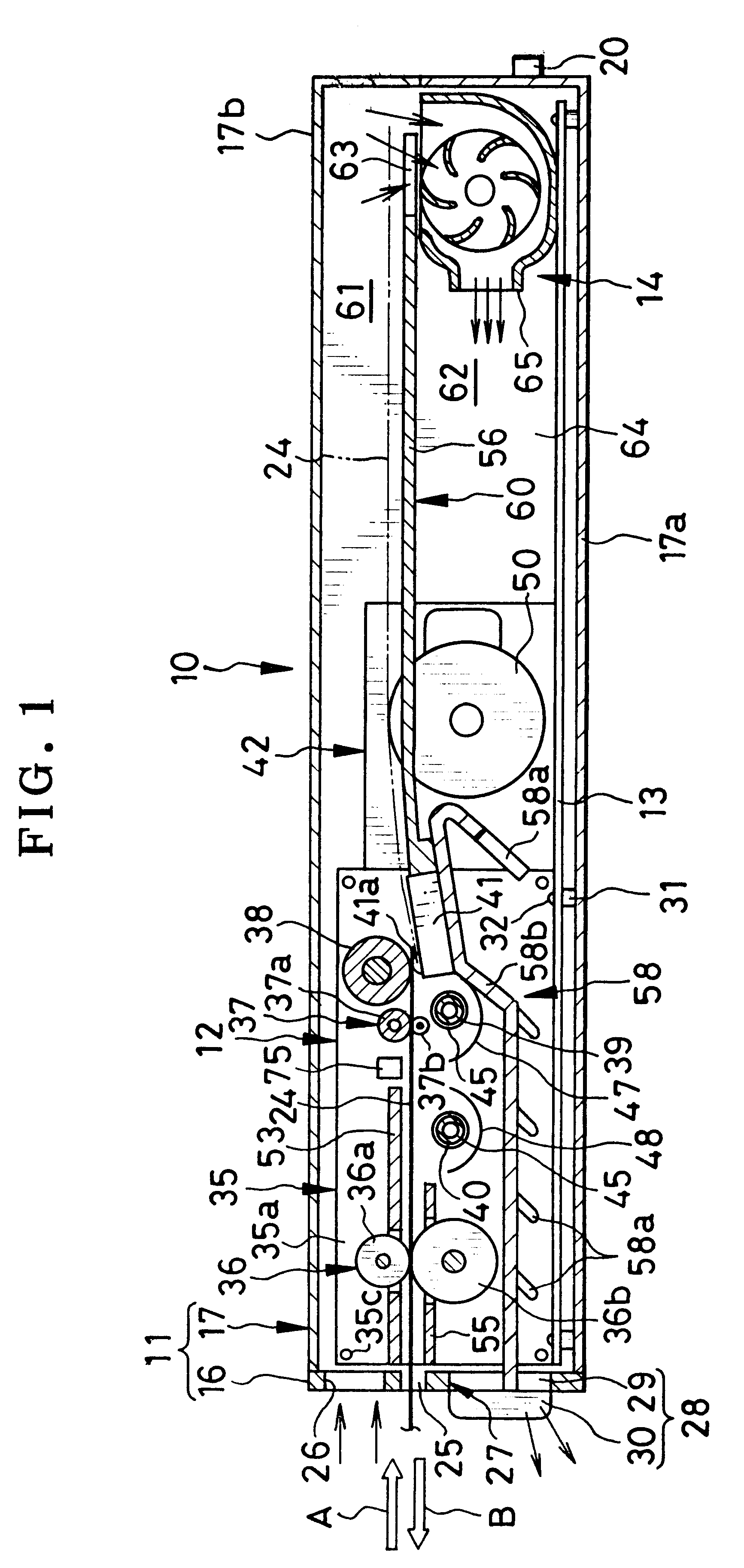
In FIG. 1, a color thermal printer 10 is illustrated in section. The thermal printer 10 is constituted by a printer casing 11, a printing unit 12, a printed circuit board 13 and a heat remover unit or cooler unit 14.

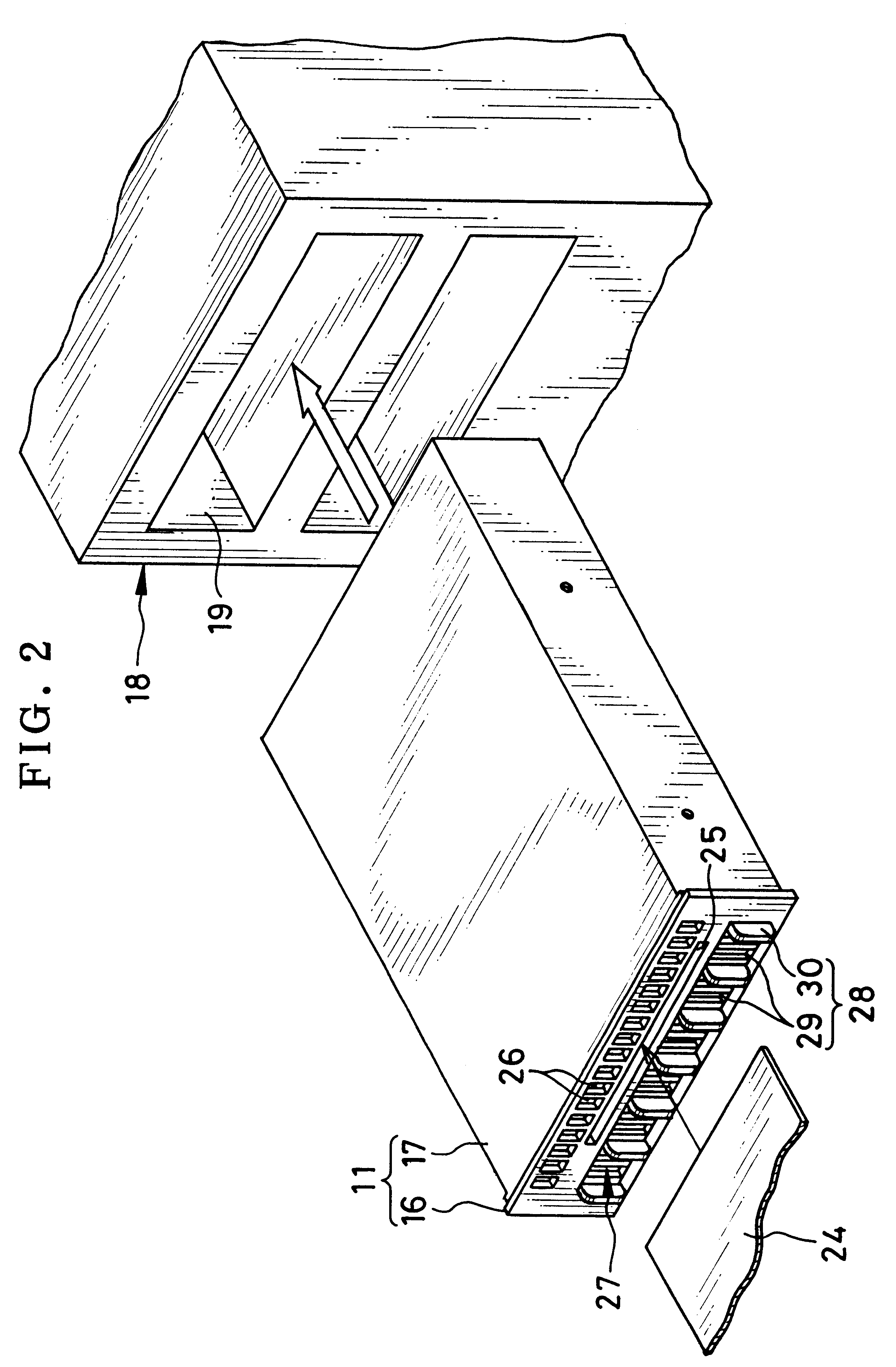
In FIG. 2, the printer casing 11 is constituted by a casing component 17 and a front panel 16, and generally has a shape of a box or rectangular parallelepiped and with a small thickness. There are screws (not shown) which secure the front panel 16 to the casing component 17. The casing component 17 has a shape and size suitable to be mounted in a bay 19 of a personal computer 18 of a tower type. In the present embodiment the casing component 17 is 146 mm wide, 41 mm high, and 220 mm deep.

In FIG. 1, the casing component 17 is constituted by lower and upper casing halves 17a and 17b, which make it easy to incorporate the printing unit 12, the printed circuit board 13 and the heat remover unit 14. The rear of the printer casing 11 has a connector 20. When the thermal print...


PUM

PropertyMeasurementUnit
sizeaaaaaaaaaa
thicknessaaaaaaaaaa
wavelengthaaaaaaaaaa

Abstract

A color thermal printer a conveyor for conveying a color thermosensitive recording sheet along a conveying path. A thermal head thermally records a full-color image to the recording sheet being conveyed. A fixer lamp applies ultraviolet rays of a predetermined range of wavelength to the recording sheet being conveyed, for optically fixing the recording sheet. In the thermal printer, a printer casing has a small height, and includes a front panel oriented vertically. An insertion opening in the front panel is adapted to insertion of the recording sheet before the recording, and ejection of the recording sheet after the recording. An air inlet and an air outlet are formed in the front panel. The insertion opening is disposed between the air inlet and the air outlet. An air passageway is disposed in the printer casing, and communicates from the air inlet to the air outlet via at least a portion of the conveying path. A fan unit is disposed in the air passageway, and causes air from the air inlet to flow along the air passageway, to cause heat generated in the printer casing to exit from the air outlet.

Description

1. Field of the InventionThe present invention relates to a thermal printer, a thermal printing method and a conveyor for recording material. More particularly, the present invention relates to a thermal printer which can be easily combined with a personal computer, a video player or the like, and a thermal printing method and a conveyor for recording material used with the thermal printer.2. Description Related to the Prior ArtA tower type of personal computer has been recently used widely. The personal computer of this type has a feature of high extensibility, and includes a plurality of so-called bays, or spaces for setting respective relevant devices such as a flexible disk (FD) drive device, a hard disk device, a compact disk (CD) drive device and an MO drive device. Each bay can contain such a peripheral unit which is approximately 146 mm wide, 41 mm high, and 220 mm deep.There is another suggestion of the personal computer in which a scanner is set in the bay with intention o...

Claims


Application Information

Patent Timeline
Patent Type & Authority Patents(United States)
IPC IPC(8): B41J13/00B41J2/32B41J29/377B41M5/34B41M5/382
CPCB41J2/32B41J13/00B41J29/377B41M5/38221B41M5/345
Inventor SASAKI, HIDEMITAKATORI, NAOKIGOTO, SATORU
Owner FUJIFILM CORP
Why Eureka
Try Eureka