Image forming apparatus with highly operable sheet discharge device

a discharge device and high-operational technology, applied in the field of image forming apparatus, can solve the problems of inconvenient user, inconvenient printing, and a newly output sheet being mixed with the sheet left on the discharge bin

Inactive Publication Date: 2001-08-28
KONICA MINOLTA INC
View PDF10 Cites 20 Cited by
  • Summary
  • Abstract
  • Description
  • Claims
  • Application Information

AI Technical Summary

Benefits of technology

Another object of the present invention is to prevent sheets discharged corresponding to a plurality of image forming jobs, if any, from being mixed up at the discharge unit in a sheet processing device connected to an image forming apparatus.
Detection such as capacity overflow is made for at least one of the plurality of second discharge trays. A sheet is transported to the first discharge tray according to the detection. Thus, a sheet processing device improved in operability can be provided.

Problems solved by technology

Such a printer is limited in the number of the discharge bins.
However, the problem of a newly output sheet being mixed up with the sheet left on the discharge bin will not be solved.
This is inconvenient for the user.
The operability in discharging a sheet is not satisfactory.
However, such a structure will increase the cost, and mixture of the discharge sheets cannot be avoided even when the output sheets are shifted and mounted for every job at the discharge bin.
Furthermore, the interval between the jobs cannot be easily detected at a glance even when shifting is carried out on the discharge bins arranged in the vertical direction.
This may cause the user inconvenience.
The operability in discharging a sheet is not of the satisfactory level.
It is to be noted that the capacity of storing sheets in the bin of the sheet output device (bin capacity) is limited.
There is a problem that, not only the operability of the user specifying the current sheet output, but also the operability of other users, will be degraded.

Method used


Image

  • Image forming apparatus with highly operable sheet discharge device
  • Image forming apparatus with highly operable sheet discharge device
  • Image forming apparatus with highly operable sheet discharge device

Examples


first embodiment

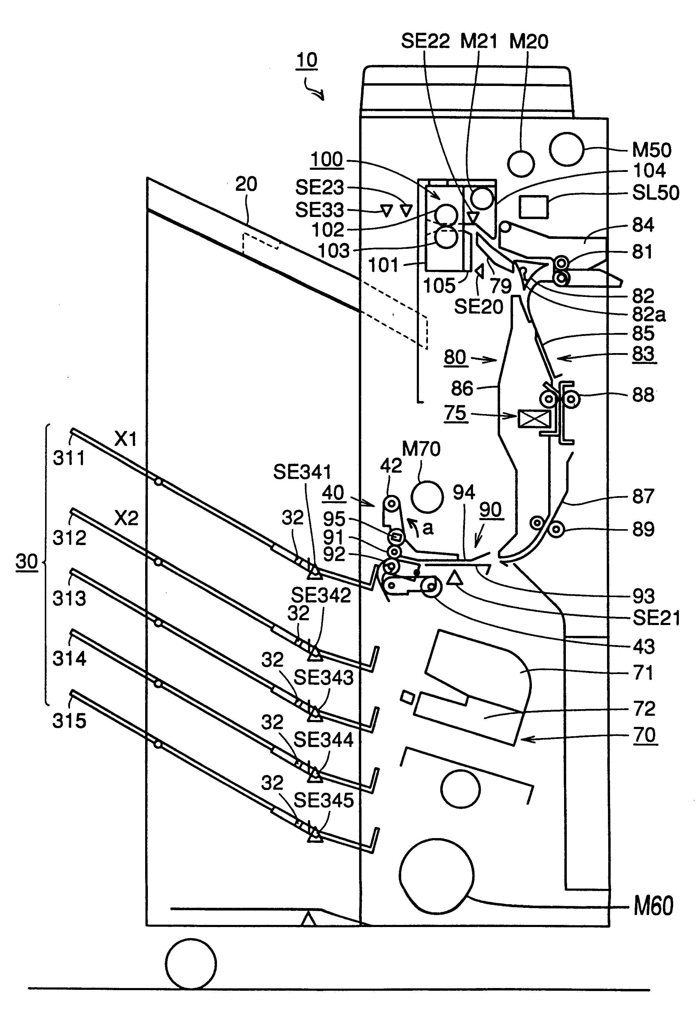
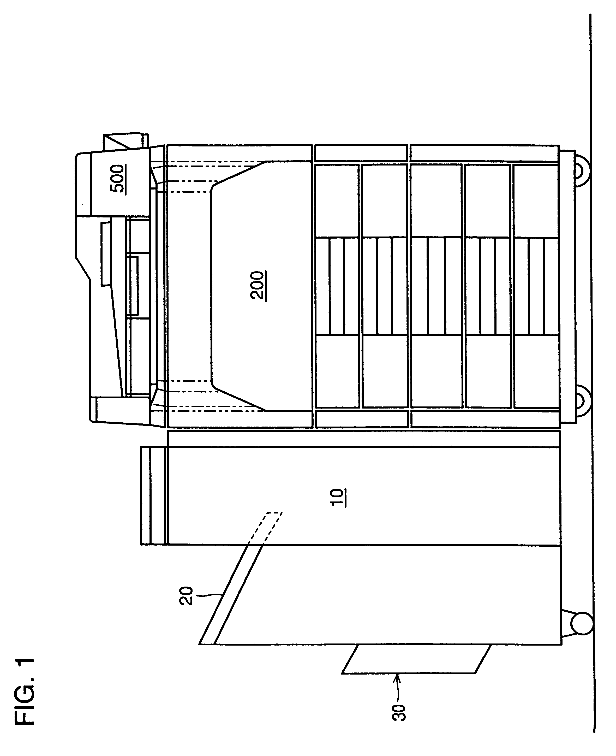
FIG. 1 is a diagram to describe an entire structure of an image forming system including a staple sorter 10 and a digital copy machine 200 connected to staple sorter 10 according to the present invention.

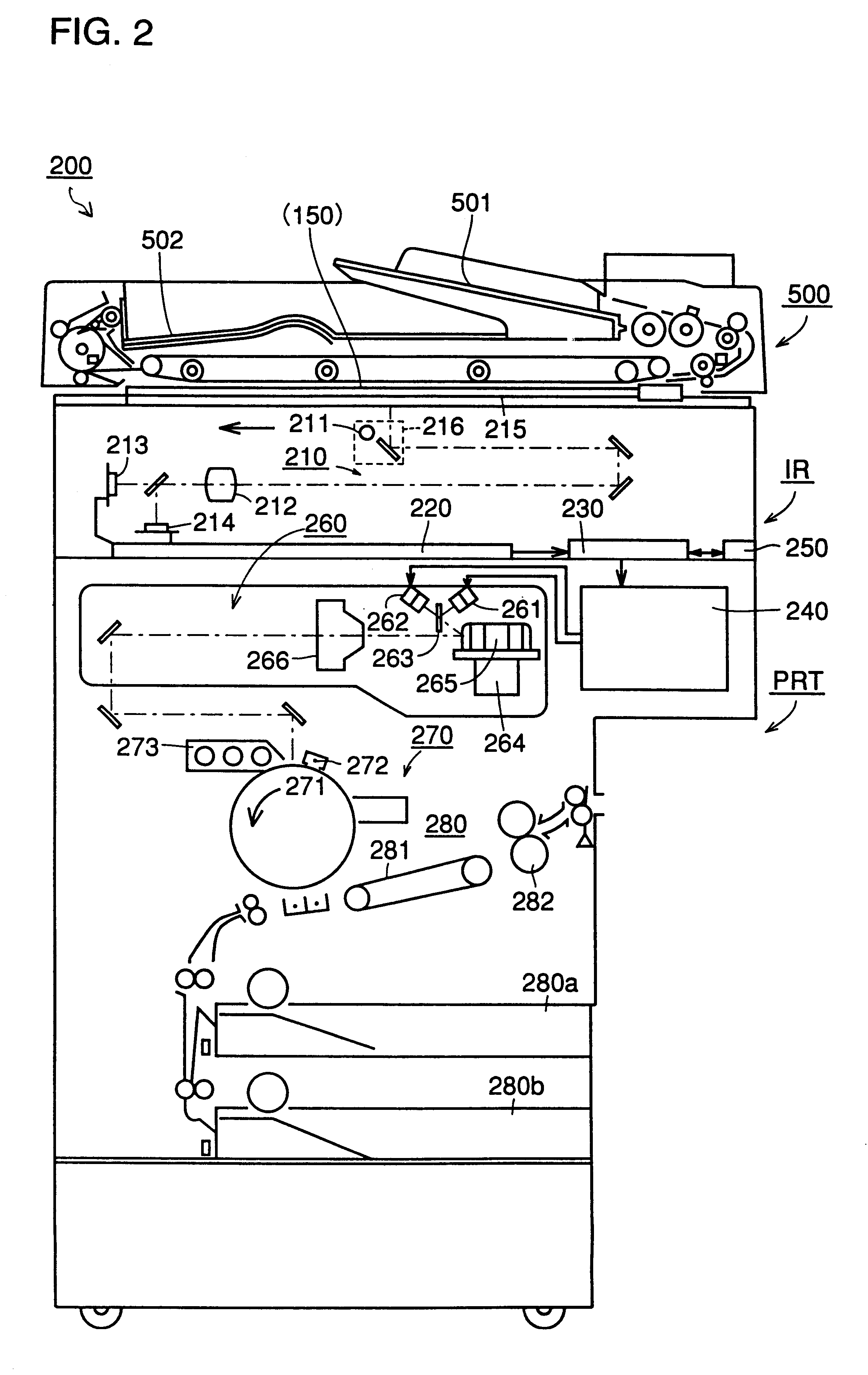
In digital copy machine 200, an operation of a user is input via an operation panel 150 (refer to FIGS. 2 and 3) in forming an image. In response to a user input, a circulation type automatic document transport device 500 mounted on digital copy machine 200 feeds out one document at a time of one group of documents placed on a predetermined document supply tray onto a glass platen. When an exposure process is applied on the document on the glass platen, document transport device 500 discharges the document on the platen glass sequentially onto a document discharge tray.

As shown in FIG. 2, digital copy machine 200 forms an image on a sheet from the image of a document read by an exposure process according to electrophotography. The sheet on which an image is formed is transferred to ...

second embodiment

An image forming system according to a second embodiment of the present invention will be described hereinafter. The image forming system of the second embodiment differs from the image forming system of the first embodiment in the control procedure of the staple sorter described with reference to FIGS. 12 and 13. The remaining elements are similar to those of the image forming system of the first embodiment.

According to the staple sorter of the image forming system of the second embodiment, a user information management table and a bin information management table shown in FIGS. 14 and 15 are generated by the CPU that controls the staple sorter. The tables are stored in the RAM connected to this CPU. Control according to the flow chart of the main routine of FIG. 16 and the flow chart of the subroutine shown in any of FIGS. 17-26 are executed using the user information management table and bin information management table.

FIG. 14 shows a user information control table formed by the...

third embodiment

An image forming system according to a third embodiment of the present invention will be described. The image forming system of the third embodiment differs from the image forming system of the first embodiment in the control procedure of the staple sorter described with reference to FIGS. 12 and 13, likewise the image forming system of the second embodiment. The remaining elements of the third embodiment is similar to that of the image forming system of the first embodiment.

According to the staple sorter of the image forming system of the third embodiment, a user information management table shown in FIG. 26 is produced by the CPU controlling the staple sorter. This table is stored in a RAM connected to this CPU. Control according to the flow chart of FIG. 27 is carried out using the table.

Referring to the user information management table of FIG. 26, "discharge set bin" is specified corresponding to "user ED". "Discharge set bin" specifies a plurality of bins provided at the stapl...


PUM

PropertyMeasurementUnit
timeaaaaaaaaaa
sizeaaaaaaaaaa
structureaaaaaaaaaa

Abstract

An image forming system includes a digital copy machine to form an image on a group of sheets from an image of a group of documents, and a staple sorter sorting and discharging copied sheets from the digital copy machine, According to the staple sorter, control is provided so that a sheet of a long left period of time is transported from the bin to a nonsort tray when all of a plurality of bins provided in the staple sorter are used during a print operation. The left time of a sheet is monitored even when a print operation is not carried out. When the left time exceeds a predetermined time, control is provided so that the sheet left in the bin is transferred to the nonsort tray. As a result, a sheet discharge device is provided improved in operability of sheet discharge.

Description

This application is based on Japanese Patent Application Nos. 10-107789 and 10-170068 filed in Japan, the contents of which are hereby incorporated by reference.The present invention relates to a sheet processing device to sort and discharge a sheet on which an image is formed, and an image forming system including this sheet processing device and an image forming apparatus.DESCRIPTION OF RELATED ARTIn an image forming apparatus including a conventional sheet processing device, there are cases when a plurality of users share one printer. In order to prevent a subsequent printed sheet from being mixed up at the sheet discharge unit, a sensor is provided to detect the presence of a sheet corresponding to each of a plurality of discharge bins to select an appropriate discharge bin to discharge a sheet.Such a printer is limited in the number of the discharge bins. When a sheet is discharged and left at all the discharge bins, discharge of another sheet will cause that sheet to be mixed ...

Claims


Application Information

Patent Timeline
Patent Type & Authority Patents(United States)
IPC IPC(8): B65H39/10G03G15/00
CPCB65H39/10G03G15/6538B65H2301/422G03G2215/00827B65H2601/421B65H2513/50B65H2513/42B65H2511/51B65H2511/415B65H2408/112B65H2408/116B65H2220/01B65H2220/02B65H33/08
Inventor YOSHIDA, AKINORITAKEMOTO, MOTOMINAITO, KOJIIKEDA, HIROAKI
Owner KONICA MINOLTA INC
Why Eureka
Try Eureka