Positional detector device for a vehicular license plate

a technology of positional detector and license plate, which is applied in the field of positional detector devices, can solve the problems of difficult detection of the position of the license plate with the methods, and achieve the effect of high precision

Inactive Publication Date: 2001-08-28
UMETECH YUGEN KAISHA
View PDF4 Cites 49 Cited by
  • Summary
  • Abstract
  • Description
  • Claims
  • Application Information

AI Technical Summary

Benefits of technology

(i) It is possible to detect the position of the license plate 41 with high precision. This makes a number read-out device (not shown) precisely read the image of the license plate 41 when the image is sent to the number read-out device.(ii) It is possible to accurately recognize the position of the license plates having the versatile patterns in which black, white and black letters are in turn drawn with white, green and yellow backgrounds.(iii) It is also possible to accurately read the position of the license plate 41 under the adverse conditions such as at the time of dawn, dusk, dark hours in bad weather days. Even when the image of the head lamp is cut off from the original image, it is possible to prevent the head lamp from mistakenly recognized.(iv) With the neural network quick in learning, it is possible to precisely detect the position of the license plate 41 with relatively small hours of the learning.

Problems solved by technology

However, especially under adverse photographing conditions, it is difficult to detect the position of the license plate with the methods (1).about.

Method used


Image

  • Positional detector device for a vehicular license plate
  • Positional detector device for a vehicular license plate
  • Positional detector device for a vehicular license plate

Examples


Embodiment Construction

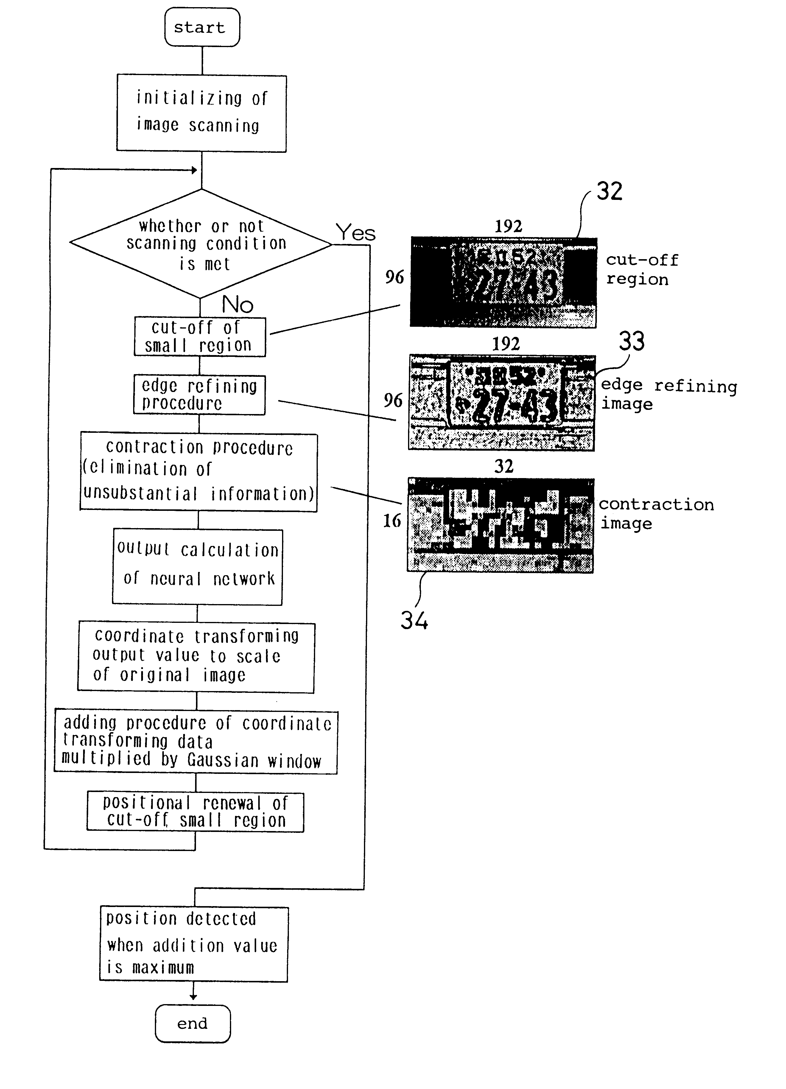
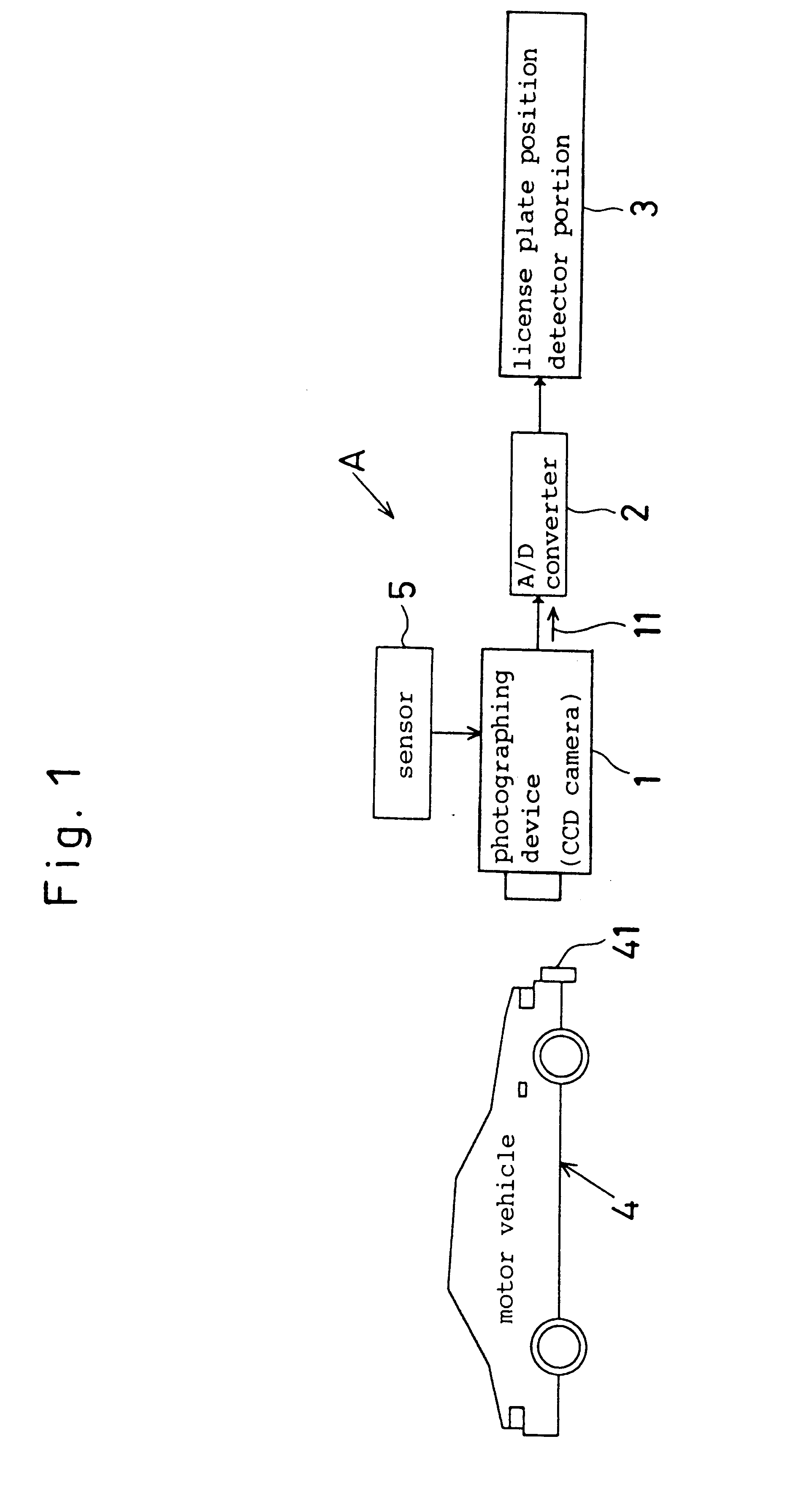
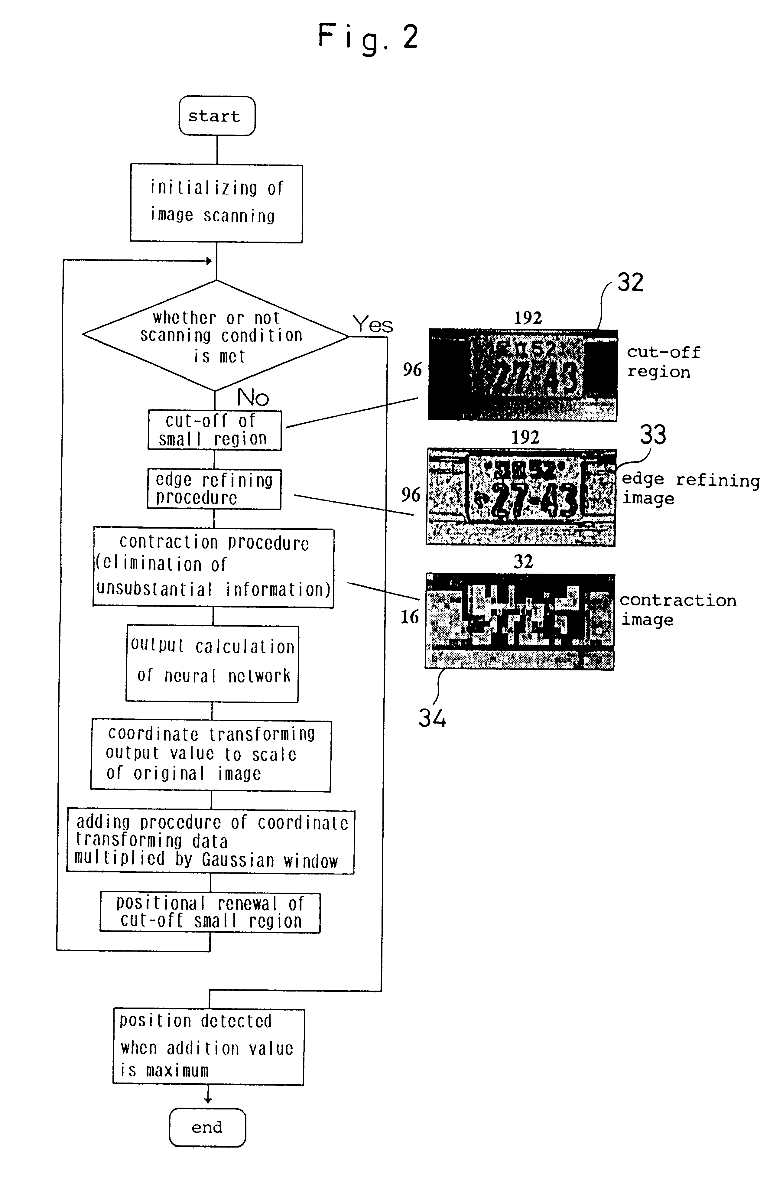
Referring to FIGS. 1 through 8, a positional detector device for a license plate has a CCD camera 1 installed on a toll gate of a parking lot or highway as shown at (A) in FIG. 1. The positional detector device (A) further has an A / D converter 2 which converts an image signal 11 into digital data. A license plate position detector portion 3 is provided to detect a position of the license plate 41 for a motor vehicle 4. The positional detector device (A) thus assembled is incorporated into a license plate reading device (not shown).

The camera 1 is placed to direct toward the coming motor vehicle 4, and adapted to photograph a frontal portion (including a license plate 41) of the motor vehicle 4 when a sensor 5 perceives that the motor vehicle 4 approaches within a predetermined distance. The photograph is reduced to an image signal 11 which is fed to the A / D converter 2 so as to change the image signal 11 into a digital image in which a size of an original image 31 is in the scale of...


PUM


Abstract

In a positional detector device for a license plate of a motor vehicle, a camera is provided to photograph a front and rear portion of a motor vehicle so as to produce an image signal. An A / D converter converts the image signal into a digital image. A positional detector detects a position of a lisence plate of a motor vehicle based on the digital image. A cut-off treatment device cuts off a specified region from an original image photographed by the camera while scanning the original image when the motor vehicle approaches the camera member within a predetermined distance. An edge refining treatment device emphasizes a contour of a pattern represented by the specified region cut off from the original image. A contraction treatment device contracts an image size of the specified region which was treated with the edge refining treatment device. A calculation treatment device feeds the contracted pattern to a learned neural network so as to calculate an output value for a positional detection neural network. A coordinate transformation device transforms the output value of the positional detection neural network to such a scale as to meet the original image. An addition treatment device adds data at specified points which were multiplied by Gaussian window so as to obtain a projective addition value after carrying out the coordinate transformation. A distinction treatment device recognizes a position of the license plate based on a maximum value on which the projective addition value falls.

Description

1. Field of the InventionThe invention relates to a positional detector device which is provided to detect license plates of motor vehicles.2. Description of Prior ArtA motor vehicle control device has been introduced to administer entrances and exits of motor vehicles by reading the number of the license plate to obtain the numerical information on such places as parking lots and highway toll gates. In order to automatically recognize the numerical information of the license plate, it is necessary to detect a position of the license plate, and isolate the number to make the number distinct.Whether or not the positional detection of the license plate is accurate significantly affects on the precision of the subsequent treatments. This is because it is particularly important to precisely carry out the positional detection of the license plate.The following methods have been introduced to detect the position of the license plate from a frontal image of the motor vehicle.(1) It is dete...

Claims


Application Information

Patent Timeline
Patent Type & Authority Patents(United States)
IPC IPC(8): G06T7/00G06T5/00
CPCG06T7/0042G06T7/0081G06T2207/30252G06T2207/10016G06T7/11G06T7/73
Inventor UMEZAKI, TAIZOKANADE, TAKEOMATSUMOTO, NORIYUKI
Owner UMETECH YUGEN KAISHA
Why Eureka
Try Eureka