Membrane filter apparatus with gas discharge cleaning means
a membrane filter and gas discharge technology, applied in the direction of filtration separation, sedimentation settling tanks, separation processes, etc., can solve the problems of increasing the energy required for filtration, affecting the permeability of the membrane element, and failure to maintain good filtration
- Summary
- Abstract
- Description
- Claims
- Application Information
AI Technical Summary
Problems solved by technology
Method used
Image
Examples
second embodiment
Next, the present invention will be described.
FIG. 10 shows a plan view of a partition unit according to a second embodiment of the present invention. FIG. 11 shows a perspective view of the partition unit according to the second embodiment.
In the second embodiment, partitions 101 and 102 are disposed within a space defined by the skirt element 71 at two widthwise opposite positions of the membrane unit 50 (FIG. 4) such that they extend along the arraying direction of the membrane elements 51. The partitions 101 and 102 are in parallel with side walls 71a and 71b of the skirt element 71. Thus, the partitions 101 and 102 and the side walls 71a and 71b define compartments 106 and 107, respectively, in a symmetric manner with respect to the center of the partition unit.
Partitions 103 and 104 are disposed within a space defined by the partitions 101 and 102 at two opposite positions located in the arraying direction of the membrane elements 51 in such a manner as to extend in the width ...
third embodiment
Next, the present invention will be described.
FIG. 12 shows a plan view of a partition unit according to a third embodiment of the present invention. FIG. 13 shows a perspective view of the partition unit according to the third embodiment.
A partition 111 is disposed within a space defined by the skirt element 71 in parallel with the side walls 71a to 71d of the skirt element 71. The partition 111 and the four side walls 71a to 71d of the skirt element 71 define a compartment 112 symmetrically with respect to the center of the partition unit. The partition 111 also defines a compartment 113 inside.
Accordingly, not only are the membrane surfaces 52 sufficiently cleaned at their opposite side edge portions as viewed in the width direction of the membrane unit 50 (FIG. 4), but also the membrane surfaces 52 located at opposite end portions of an array of the membrane elements 51 can be sufficiently cleaned.
fourth embodiment
Next, the present invention will be described.
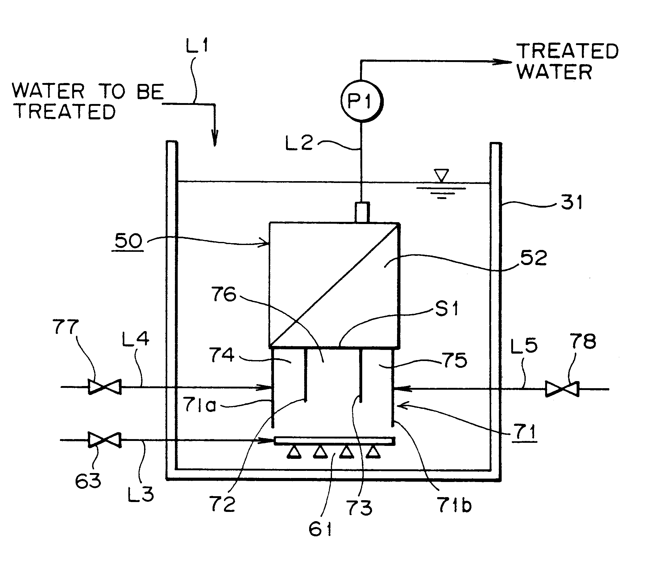
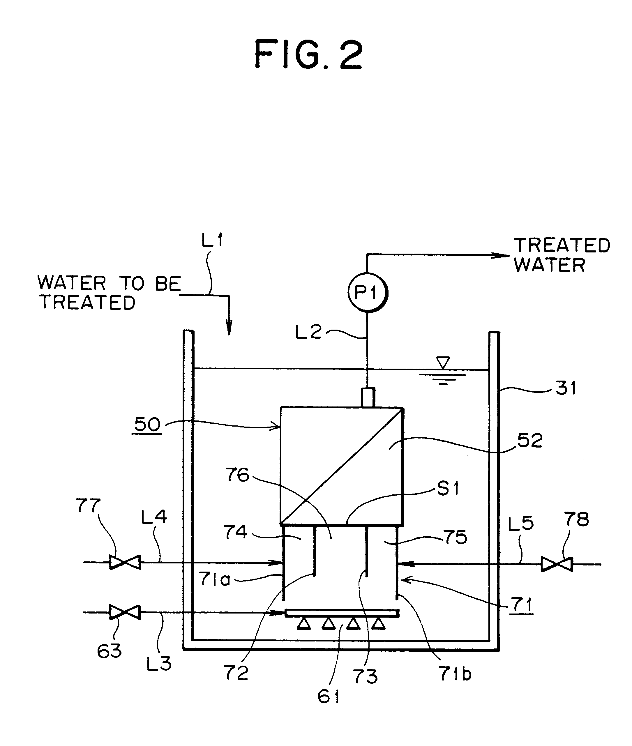
FIG. 14 shows a schematic view of a membrane filter apparatus according to a fourth embodiment of the present invention. FIG. 15 shows a perspective view of a main portion of the membrane filter apparatus according to the fourth embodiment. The same features as those of the first embodiment are denoted by common numerals, and their description will be omitted.
Partitions 172 and 173 are disposed within a space defined by the skirt element 71 at two widthwise opposite positions of the membrane unit 50 such that they extend along the arraying direction of the membrane elements 51 (FIG.4). The partitions 172 and 173 are slanted with respect to the side walls 71a and 71b of the skirt element 71. The partitions 172 and 173 and the side walls 71a and 71b define compartments 174 and 175, respectively, whereas the partitions 172 and 173 define a compartment 176.
Since the partitions 172 and 173 are slanted such that their bottom ends are biased to...
PUM
| Property | Measurement | Unit |
|---|---|---|
| linear velocity | aaaaa | aaaaa |
| width | aaaaa | aaaaa |
| distance | aaaaa | aaaaa |
Abstract
Description
Claims
Application Information
 - R&D
- Intellectual Property
- Life Sciences
- Materials
- Tech Scout
- Unparalleled Data Quality
- Higher Quality Content
- 60% Fewer Hallucinations
Browse by: Latest US Patents, China's latest patents, Technical Efficacy Thesaurus, Application Domain, Technology Topic, Popular Technical Reports.
© 2025 PatSnap. All rights reserved.Legal|Privacy policy|Modern Slavery Act Transparency Statement|Sitemap|About US| Contact US: help@patsnap.com


