
Solar generator with foldable panels especially for a spacecraft

a solar generator and spacecraft technology, applied in electrochemical generators, cosmonautic vehicles, batteries, etc., can solve the problems of affecting the flight of the spacecraft, requiring substantial effort and expense, and testing such generators with flap open motion under earth gravity conditions, so as to avoid or avoid generating undesirable torque moments

Inactive Publication Date: 2001-09-04
DAIMLER AG
View PDF4 Cites 33 Cited by
  • Summary
  • Abstract
  • Description
  • Claims
  • Application Information

AI Technical Summary

Benefits of technology

to avoid drawbacks of conventional solar collectors, more specifically to provide folding and unfolding features that will avoid or at least substantially reduce imposing of disturbing moments onto the spacecraft to which the collector is mounted;
to combine rotational folding movements of individual first panels relative to each other with compound movements including lateral, linear motion components of second panels to avoid generating undesirable torque moments;
An important advantage of the solar generator according to the invention is its ability to have a substantially larger collector surface area without increasing the collector length away from the spacecraft compared to conventional collectors. Further, the folding and unfolding of the present solar collector panels does not exert on the spacecraft torque moments that could have an adverse influence on the spacecraft or space flight body. Still another advantage is seen in that the foldability of the present collector panels is highly reliable because simple articulation hinges and coupling journal elements are employed. It is unexpected that the combination of two motion directions for the folding and unfolding of the panels is as reliable as the folding and unfolding of a conventional panel combination that permits folding and unfolding in only one direction. Moreover, the present folding operations can be tested on the ground under gravity conditions with little effort and expense.

Problems solved by technology

The total deployed surface area of such solar collectors is limited by the acceptable maximal longitudinal extension of the panels away from the body of the satellite.
However, flapping open the panels of the second group causes relatively large disturbing moments that adversely affect the flight of the spacecraft.
Another drawback is the fact that testing such generators with flap open motions under earth gravity conditions require a substantial effort and expense.
However, deployment can be problematic.

Method used


Image

  • Solar generator with foldable panels especially for a spacecraft
  • Solar generator with foldable panels especially for a spacecraft
  • Solar generator with foldable panels especially for a spacecraft

Examples


second embodiment

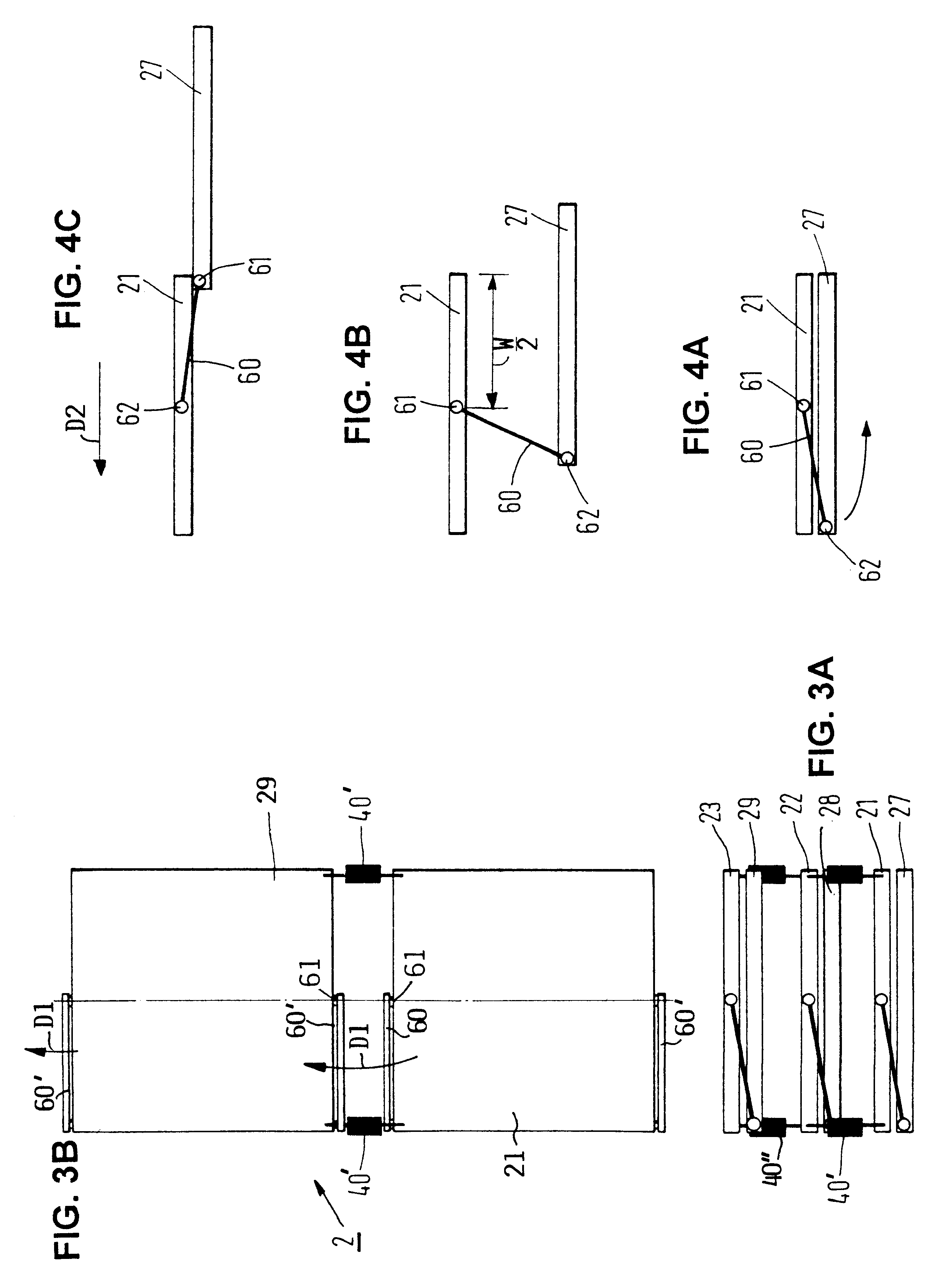
A second embodiment will now be described with reference to FIGS. 3A, 3B, 4A, 4B, 4C, 7C and 7D. In this embodiment each packet of the solar collector 2 comprises two panels as best seen in FIG. 4A. Panels 20, 21, 22 and 23 are referred to as first panels which are hinged to each other by the hinges 40' and 42" as described above with reference to the first example embodiment. Accordingly, the first panels can be unfolded in the manner of pleats of a bellows in the first direction D1. Second panels 27, 28 and 29 are coupled to the first panels only along one side thereof as shown in FIG. 7C. In another arrangement of second panels, the second panels 25, 27 and 29 are coupled to the first panels as shown in FIG. 7D showing the panel 25 on one side of the first panels and staggered relative to the second panels 27, 29 on the other side of the first panels. Here again, the first panels are foldable and unfoldable in the direction D1 while the second panels are laterally shiftable with ...


PUM


Abstract

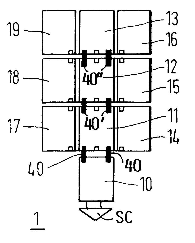
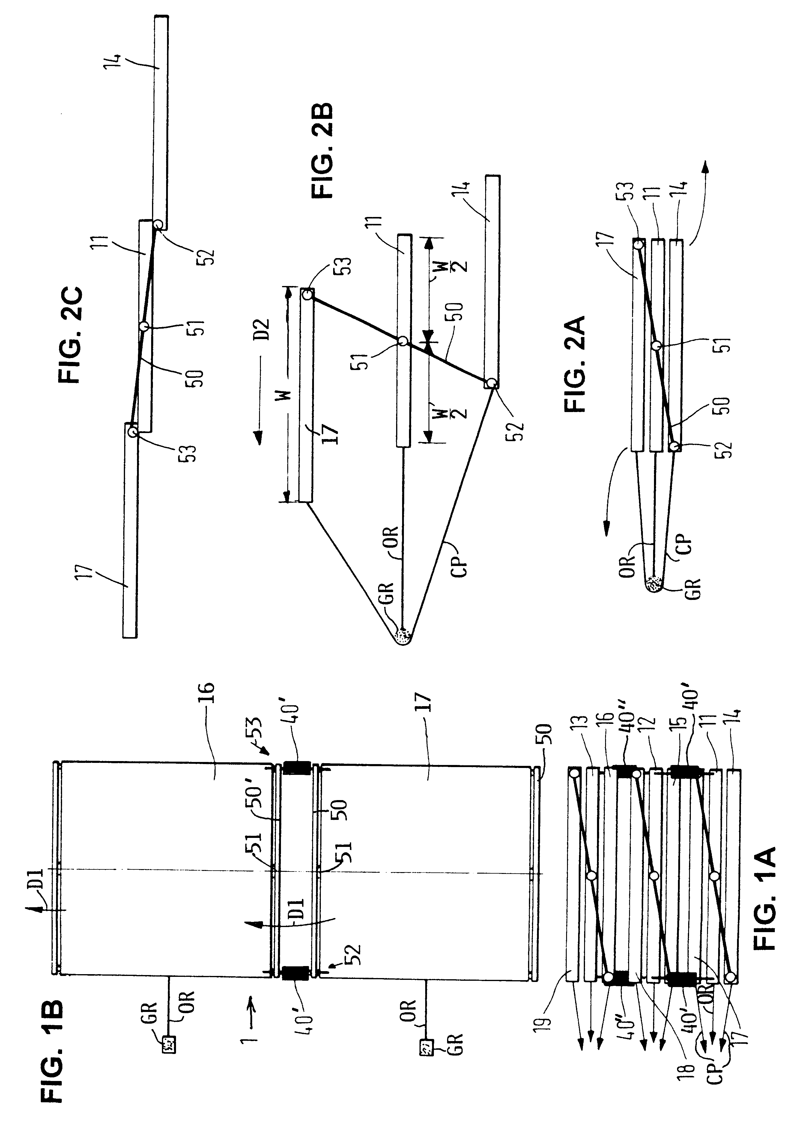
A solar generator especially for a spacecraft or space flight body has a plurality of first collector panels hinged to each other in a column extending in a first direction (D1) when the first collector panels are unfolded and a plurality of second panels coupled to the first panels so that the second panels can be unfolded in a second direction (D2) only after the first panels have been unfolded. The second panels are coupled to the first panels by journal struts or by hinges so that at least one first panel forms with at least one second panel, preferably with two or more second panels, a panel packet. The hinges (40) that articulate the first panels to each other permit unfolding the panel packets in said first direction (D1), whereupon the second panels in the individual packets can be unfolded in the second direction (D2).

Description

The invention relates to a solar generator, particularly for spacecraft. The solar generator or collector comprises panels that are stowed as a packet for transport and unfolded for deployment.BACKGROUND INFORMATIONSolar generators or collectors are commonly used as power supplies for spacecraft such as telecommunication satellites. The terms "generator" and "collector" are used interchangeably herein. Solar collectors have panels that are initially folded for stowing the collector while transporting the satellite into an earth orbit. The panels are unfolded into an open state for deployment when the orbit has been reached. During the transport phase the collector shall need as little space as possible. On the other hand, the deployed surface area shall be as large as possible for transforming solar energy into electrical energy. Moreover, the deployment of the collector must be possibly free of trouble in order not to imperil the satellite's mission. Thus, a high degree of reliabil...

Claims


Application Information

Patent Timeline
IPC IPC(8): B64G1/44B64G1/22B64G1/42H01L31/045
CPCB64G1/222H02S30/20B64G1/443Y10S136/292Y02E10/50
Inventor HAKAN, ALOSEIFERT, FRANK
Owner DAIMLER AG
Learn More